Un0rick Save
smallish ice40 / raspberrypi ultrasound hardware


![]()
![]()
un0rick
Overview
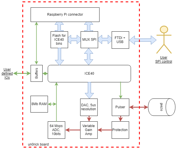
This is a relatively simple single-channel ultrasound board. Block diagram below:
Step-by-step
- Program the fpga using a open-source toolchain to synthetise the embedded firmware.
- Control the board fully through SPI, be it through USB, a Raspberry Pi, or even an arduino (though a cheap one may not have sufficient resources to do what you want do to).
- Set up the acquisition sequence
- Get the data back again
- Process / visualize the acquistion
I recommend using RPi, particularly W for the wireless aspects, which then becomes the board server. There's a dedicated 20x2 header. Prepared is a python lib as well. The v1.0.0 version is RPi4 proofed.
Two control options: usb or raspberry
Examples
- With a Raspberry pi
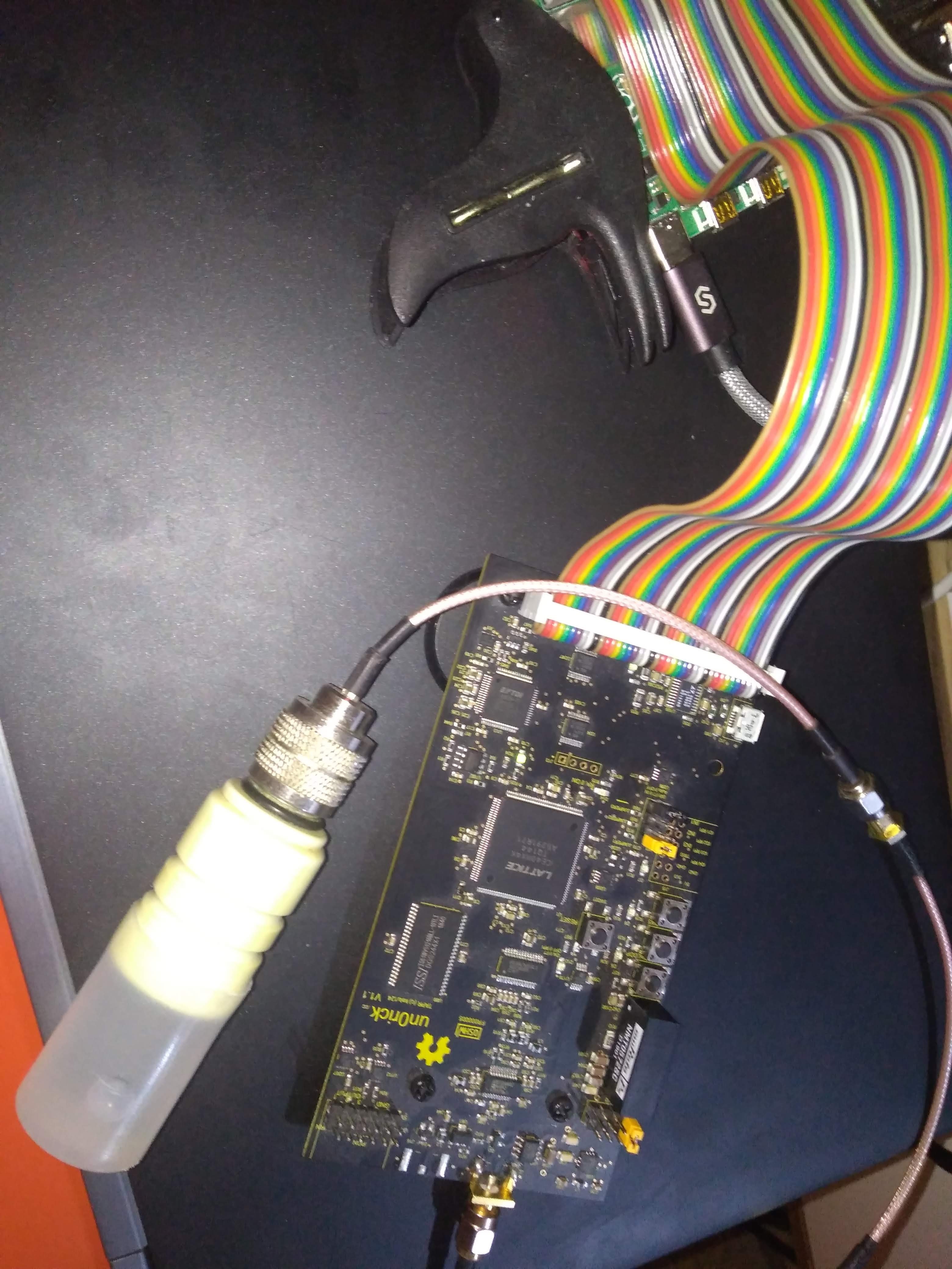
The board was connected to a single element piezo, in water, with a reflector a few centimers away, immersed in water. Pulser is set up at 25V high pulses. Control was done through a Raspberry Pi W which is used as a controler and server, another Rasbperry pi.
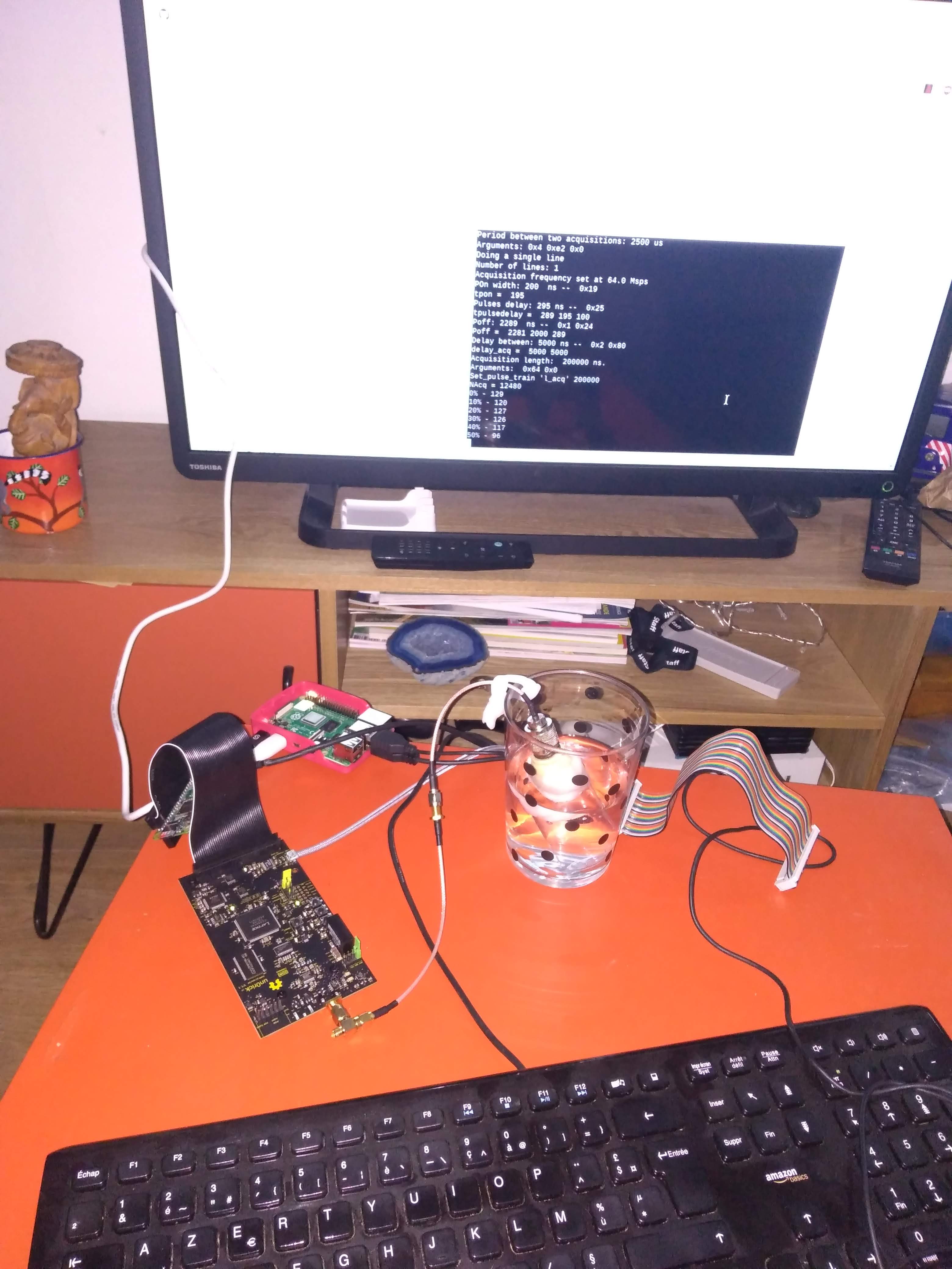
Acquisition is realized, with a small offset, between 32Msps and 64Msps. Data is explored a bit further.
- With a M5Stack (or any microcontroller really)
The board was also tested with a nice m5stack board (ino file). Below an example in image:
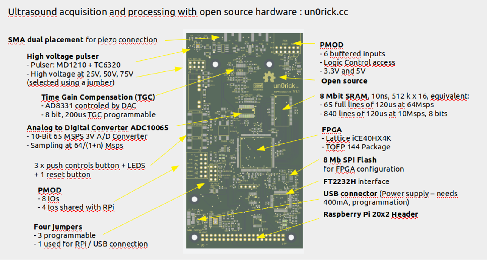
Specs (un0v1.1)
- FPGA: Lattice iCE40HX4K - TQFP 144 Package
- Memory:
- 8 Mbit SRAM, 10ns, 512 k x 16, equivalent to 65 full lines of 120us at 64Msps or 840 lines of 120us at 10Msps, 8 bits.
- 8 Mb SPI Flash for FPGA configuration
- Ultrasound processing:
- VGA: AD8331 controled by DAC
- Pulser: MD1210 + TC6320
- ADC: 65Msps ADC10065
- Data formatted over 2 bytes, with 10 bits / sample, 2 bits of line trackers, 4 bits of IOs (counters, ...) and 2 bits for tracking.
- Parameters: Settings programable via USB or Raspberry Pi
- Type of acquisition (one line / set of lines)
- Number of lines
- Length of lines acquisitions
- Delay between acquisitions
- Pulse width
- Delay between pulse and beginning of acquisitions
- 200us time-gain-compensation programmable (8 bits, from 0 to Max), every 5us
- Extensibility:
- 2 x Pmod connectors
- SMA plug for transducers
- RPi GPIO
- User Interfaces:
- 2 x PMOD for IOs
- 4 x push button (with software noise debouncing)
- Jumpers for high voltage selection
- Jumpers for SPI selection
- Input Voltage:
- 5 V from RPi or USB
- Uses 350mA-450mA at 5V (including RPi)
- Operating Voltage:
- FPGA and logics at at 3.3 V
- High voltage at 25V, 50V, 75V
- Fully Open Source:
- Hardware: github repository
- Software: github repository
- Toolchain: Project IceStorm
- Documentation: gitbook
Latest sources
- Hardware resources are on github:
- FPGA bin so far using Lattice's tools. A icestorm port is coming.
- Files for v1.1 and v1.01 are available - on upverter too.
- FPGA files too:
- Python lib too
Orders
- The board is available on Tindie at around 489$.
- Send me a mail at [email protected] !
- Or wait for the Tindie shop
Others
Changelog
- lit3rick v1.4
- Using AD8332 for more gain
- ADC: 12bits -> 10bits
-
lit3rick v1.3
- lighter board
- 12bits ADC
- up5k based
- external HV modules
- un0rick dual _v1.2 - to be done
- Better HV generation
- SPI muxing to update
- Check USB too
- PMOD-compliant headers
- remove i2c header, but keep i2c to RPI (with PU)
- un0rick dual - v1.1
- Double SMA to possibly separate TX and RX path (for dual elements transducers)
- Still some issues with muxing
- un0rick - v1.01
- Rewired SPI
- Less MUXing
- The "matty board" v1
- First ice40 board - compatible with iceprog =)
- Only one in existence, had some SPI wiring issues
- HV module footprint reversed
Tip: reaching 128msps
Playing with the trigger, it's possible to interleave two signals and artificially double to acquisition speed, yielding clean images.
Overview
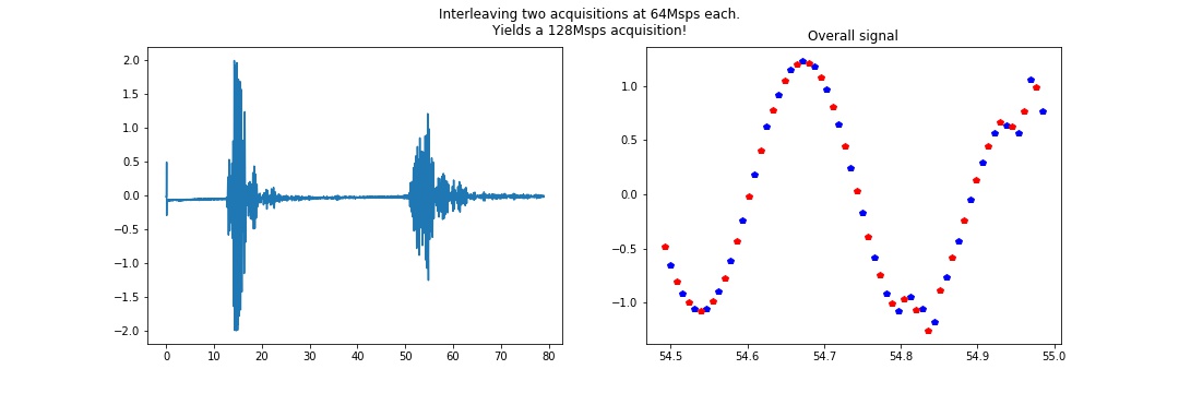
In detail
It seems that the different series interleave quite nicely, even in the detail.

Useful links
- Come and chat : join the Slack channel
- The full GitHub Repo for the hx8k board.
- The board's Tindie shop
- The project Hackaday page
- A messy braindump with all experiments, and a slightly cleaner documentation of earlier works.
- un0rick boards are open-source certified on OSHWA, FR000005. lit3rick's certification is done on OSHWA, FR000006.
- wlmeng11's SimpleRick for a analog part board. Clever use of RTL-sdr hardware for the acquisition !
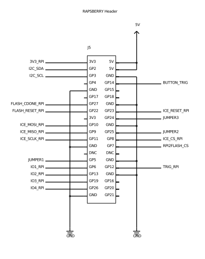
Pinouts
Raspberry Pi header
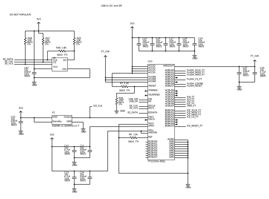
FTDI breakout
Thanks & shouts
- BiVi - always here to chat
- Charles - bringing neat insights
- David - what would I have done without you?
- echOmods - the fundations of this work
- Fabian - already so many insights
- Fouad.. and team - awesome works there
- Jan - piezooos
- Johannes and Felix - hardware is .. hard, but rew-harding!
- Sofian - early ideas!
- Sterling - another geek
- Tindie - to allow people sharing their niche hardware, and for others to search for these
- Visa - exploring amode
- Vlad - you pulse
- Wlmeng11 - inspiring
- All the supportive users
- .. and all the others around the world!
License
This work is based on a previous TAPR project, the echOmods project. The un0rick project and its boards are open hardware and software, developped with open-source elements.
Copyright Kelu124 ([email protected]) 2018
- The hardware is licensed under TAPR Open Hardware License (www.tapr.org/OHL)
- The software components are free software: you can redistribute it and/or modify it under the terms of the GNU General Public License as published by the Free Software Foundation, either version 3 of the License, or (at your option) any later version.
- The documentation is licensed under a Creative Commons Attribution-ShareAlike 3.0 Unported License.
Disclaimer(s)
This project is distributed WITHOUT ANY EXPRESS OR IMPLIED WARRANTY, INCLUDING OF MERCHANTABILITY, SATISFACTORY QUALITY AND FITNESS FOR A PARTICULAR PURPOSE. See the GNU General Public License for more details. Also:
- This is not a medical ultrasound scanner! It's a development kit that can be used for pedagogical and academic purposes - possible immediate use as a non-destructive testing (NDT) tool, for example in metallurgical crack analysis.
- As in all electronics, be careful, especially.
- This is a learning by doing project, I never did something related -> It's all but a finalized product.
- Ultrasound raises questions. In case you build a scanner, use caution and good sense!
