NeoTRNG Save
🎲 A Tiny and Platform-Independent True Random Number Generator for any FPGA (and ASIC).
The neoTRNG True Random Number Generator
A Tiny and Platform-Independent True Random Number Generator for any FPGA (and even ASICs).


![]()
- Introduction
- Top Entity, Integration and Interface
- Theory of Operation / Architecture
- Evaluation
- Hardware Utilization
- Simulation
- References
Introduction
The neoTRNG aims to be a small and platform-agnostic TRUE random number generator (TRNG) that can be synthesized for any target technology (FPGAs and even ASICs). It is based on simple free-running ring-oscillators, which are enhanced by a special technique in order to allow synthesis for any platform. The phase noise that occurs when sampling free-running ring-oscillators is used as physical entropy source.
This project is a "spin-off" from the NEORV32 RISC-V Processor where the neoTRNG is implemented as default SoC module.
Key Features
- technology, vendor and platform/technology independent - can be synthesized for any platform
- tiny hardware footprint (less than 100 LUT4s/FFs for the standard configuration)
- high throughput (for a physical TRNG)
- fully open source with a permissive license
- full-digital design; single-file VHDL module without any dependencies
- very high operating frequency to ease timing closure
- easy to use / simple integration
- full documentation down to rtl level + evaluation
[!CAUTION] It is possible that there might be at least some cross correlations between internal/external signals/events and the generated random numbers. Hence, there is no guarantee at all the neoTRNG provides perfect or even cryptographically secure random numbers! See the provided evaluation results or (even better) test it by yourself. Furthermore, there is no tampering detection mechanism or online health monitoring available yet to check for integrity/quality of the generated random data.
[!WARNING] Keeping the neoTRNG permanently enabled will increase dynamic power consumption and might also cause local heating of the chip (when using very large configurations). Furthermore, additional electromagnetic interference (EMI) might be emitted by the design.
Top Entity
The whole design is based on a single VHDL file
(rtl/neoTRNG.vhd) that
has no dependencies like special libraries, packages or submodules.
entity neoTRNG is
  generic (
    NUM_CELLS     : natural := 3;    -- number of ring-oscillator cells
    NUM_INV_START : natural := 5;    -- number of inverters in first cell, has to be odd
    SIM_MODE      : boolean := false -- enable simulation mode (use pseudo-RNG)
  );
  port (
    clk_i    : in  std_ulogic; -- module clock
    rstn_i   : in  std_ulogic; -- module reset, low-active, async, optional
    enable_i : in  std_ulogic; -- module enable (high-active)
    data_o   : out std_ulogic_vector(7 downto 0); -- random data byte output
    valid_o  : out std_ulogic  -- data_o is valid when set
  );
end neoTRNG;
Interface and Configuration
The neoTRNG uses a single clock domain driven by the clk_i signal. The module's reset signal rstn_i
is optional (tie to '1' if not used). Random data is obtained by using a simple data/valid interface:
whenever a new valid random byte is available the valid_o output will be high for exactly one cycle so
the data_o output can be sampled by the user logic.
The enable_i signal is used to initialize and start the TRNG. Before the TRNG can be used this signal
should be kept low for at least several 100 clock cycles (depending on the configuration) to ensure that
all bits of the internal shift registers are cleared again. When enable_i is set and valid_o becomes
set for the first time the TRNG is operational. Disabling the TRNG also requires enable_i being low for
the same amount of clock cycles. When enable_i gets low all ring-oscillators will be stopped reducing
dynamic switching activity and power consumption.
Three generics are provided to configure the neoTRNG. NUM_CELLS defines the total number of entropy
cells. NUM_INV_START defines the number of inverters (= the length of the ring-oscillator) in the very
first cell. These two generics are further described in the Architecture section below.
The last generic SIM_MODE can be set to allow simulating of the TRNG within a plain RTL
simulation.
Architecture
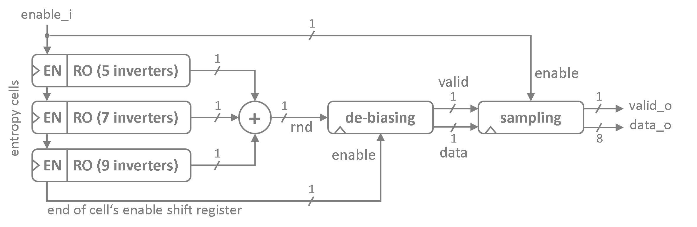
The neoTRNG is based on a configurable number (NUM_CELLS) of entropy cells. Each cell
provides a simple a ring-oscillator ("RO") that is built using an odd number of inverters. The oscillation
frequency of the RO is defined by the propagation delay of the elements within the ring. This frequency is
not static as it is subject to minimal fluctuations caused by thermal noise electronic shot noise. The
state of the RO's last inverter is sampled into a flip flop by using a static clock (clk_i). As the RO's
frequency chaotically varies over time the inherent phase noise of the sampled data is used as actual
entropy source.
Each entropy cell generates a 1-bit stream of random data. The outputs of all cells are mixed using a wide XOR gate before the stream is de-biased by a simple randomness extractor. Several de-biased bits are sampled / de-serialized by the sampling unit to provide byte-wide random number. The sampling unit also applies a simple post-processing in order to improve the spectral distribution of the random numbers.
Entropy Cells
Each entropy cell consists of a ring-oscillator that is build from an odd number of inverting latches.
The length of ring in the very first entropy cell is defined by the NUM_INV_START generic. Every
additional entropy cell adds another 2 inverters to this initial chain length. Hence, each additional
entropy cell oscillates at a lower frequency then the one before.
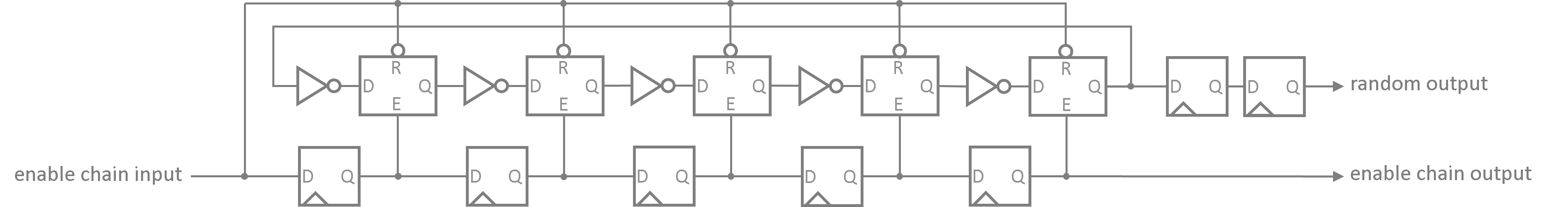
Asynchronous elements like ring-oscillators are hard to implement in a platform-independent way as they usually require the use of platform-/technology-specific primitives, attributes or synthesis settings. In order to provide a real target-agnostic architecture, which can be synthesized for any target technology, a special technique is applied: each inverter inside the RO is followed by a latch that provides a global reset and also an individual latch-enable to switch the latch to transparent mode.
The individual latch-enables are controlled by a long shift register that features a distinct FF for every single latch in the RO chain. When the TRNG is enabled, this shift register starts to fill with ones. Thus, the latches are individually enabled one-by-one making it impossible for the synthesis tool to trim any logic/elements from the RO chain as the start-up states of each latch can (theoretically) be monitored by external logic. The enable shift register of all entropy cells are daisy-chained to continue this start-up procedure across the entire entropy array.
The following image shows the simplified schematic of the very first entropy cell consisting of 5 inverter-latch elements for the rings oscillator, 5 flip flops for the enable shift register and another 2 flip flops for the synchronizer.
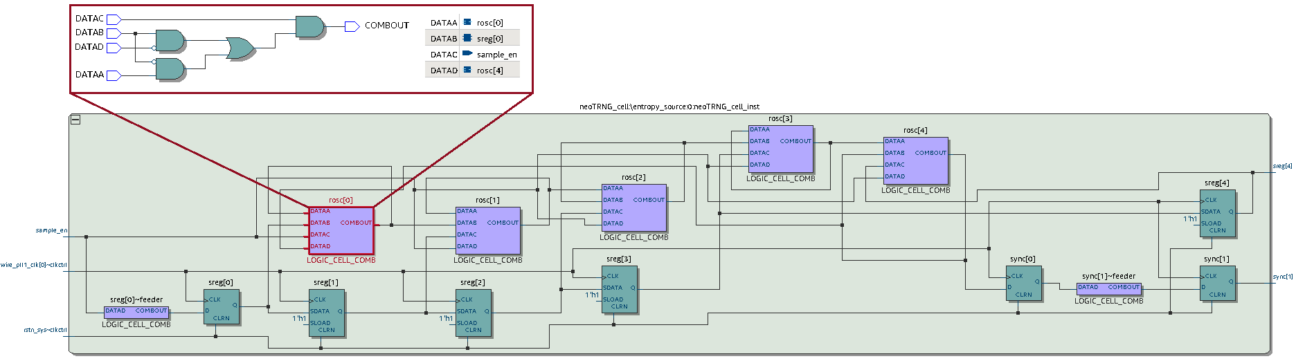
An image showing the FPGA the mapping result (generated by Intel Quartus Prime) of the very first entropy cell can be seen here. It shows that all latch+inverter elements of the ring-oscillator chain were successfully mapped to individual LUT4s.
De-Biasing
As soon as the last bit of the entropy cell's daisy-chained enable shift register is set the de-biasing unit gets started. This unit implements a simple "John von Neumann Randomness Extractor" to de-bias the obtained random data stream. The extractor implements a 2-bit shift register that samples the XOR-ed random bit from the entropy cell array. In every second cycle the extractor evaluates the two sampled bits to check a non-overlapping pair of bits for edges.
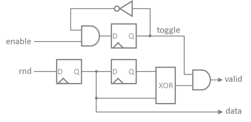
Whenever an edge has been detected a "valid" signal is send to the following sampling unit. A rising-edge
(01) emits a 1 data bit and a falling-edge (10) emits a 1 data bit. Hence, the de-biasing unit
requires at least two clock cycles to generate a single random bit. If no edge is detected (00 or 11)
the valid signal remains low and the sampling unit halts.
Sampling Unit
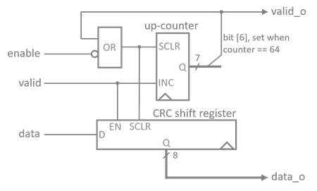
The sampling unit implements a 8-bit shift register to convert the serial de-biased bitstream into byte-wide random numbers. Additionally, the sample unit provides a simple post processing to improve the spectral distribution of the obtained random samples.
In order to generate one byte of random data the sampling unit reset its internal shift register to all-zero and starts consuming in 64 bits of the de-biased random stream. The shift register is implemented as linear-feedback shift register (LFSR) that XORs the input stream with the last bit of the register to further scramble the random bitstream.
Evaluation
The neoTRNG is evaluated as part of the NEORV32 processor, where the
neoTRNG is available as standard SoC module. The processor was synthesized for an Intel Cyclone IV EP4CE22F17C6N
FPGA running at 100MHz. For the evaluation the very small default configuration has been used: three entropy
cells are implemented where the first one implements 5 inverters, the second one implements 9 inverters and the
third one implements 11 inverters. More complex configurations with more/larger entropy cells might provide
"better" random quality.
NUM_CELLS     = 3
NUM_INV_START = 5
SIM_MODE      = false
[!NOTE] A total amount of 4MB of random data has been obtained for the evaluations. This data set is available as
entropy.binbinary file in the release assets.
Histogram Analysis
For the simple histogram analysis 4MB of random bytes were sampled from the neoTRNG. The obtained bytes were accumulated according to their occurrence and sorted into bins where each bin represents one specific byte pattern (1 byte = 8 bits = 256 different patterns). The resulting was then analyzed with regard to its statistical properties:
- arithmetic mean of all sampled random bytes
- average occurrence across all bit patterns
- min and max occurrences and deviation from the average occurrence
[NOTE] integer numbers only
Number of samples: 4194304
Arithmetic mean:   127 (optimum would be 127)

Histogram occurrence
Average:      16384 (optimum would be 4194304/256 = 16384)
Min:          16051 = average - 333 (deviation) at bin 183 (optimum deviation would be 0)
Max:          16706 = average + 322 (deviation) at bin 144 (optimum deviation would be 0)
Average dev.: +/- 96 (optimum would be 0)
Entropy per Byte
$ ent entropy.bin
Entropy = 7.994306 bits per byte.

Optimum compression would reduce the size
of this 4194304 byte file by 0 percent.

Chi square distribution for 4194304 samples is 16726.32, and randomly
would exceed this value less than 0.01 percent of the times.

Arithmetic mean value of data bytes is 127.9417 (127.5 = random).
Monte Carlo value for Pi is 3.132416851 (error 0.29 percent).
Serial correlation coefficient is 0.000496 (totally uncorrelated = 0.0).
FIPS 140-2 RNG Tests
$ rngtest < entropy.bin
rngtest 5
Copyright (c) 2004 by Henrique de Moraes Holschuh
This is free software; see the source for copying conditions.  There is NO warranty; not even for MERCHANTABILITY or FITNESS FOR A PARTICULAR PURPOSE.

rngtest: starting FIPS tests...
rngtest: entropy source drained
rngtest: bits received from input: 33554432
rngtest: FIPS 140-2 successes: 1676
rngtest: FIPS 140-2 failures: 1
rngtest: FIPS 140-2(2001-10-10) Monobit: 0
rngtest: FIPS 140-2(2001-10-10) Poker: 0
rngtest: FIPS 140-2(2001-10-10) Runs: 1
rngtest: FIPS 140-2(2001-10-10) Long run: 0
rngtest: FIPS 140-2(2001-10-10) Continuous run: 0
rngtest: input channel speed: (min=138.214; avg=1557.190; max=2119.276)Mibits/s
rngtest: FIPS tests speed: (min=32.660; avg=106.337; max=111.541)Mibits/s
rngtest: Program run time: 330110 microseconds
Dieharder Random Number Testsuite
The dieharder random number testsuite (wikipedia, homepage) by Robert G. Brown is a great toolset to stress-test and characterize random number generators.
[!IMPORTANT] :construction: work in progress :construction:
The dieharder needs a large set of random samples (something around 4GB). Otherwise, the random data is rewind obviously reducing overall entropy. Right now I am using a simple UART connection to transfer data from a FPGA to the PC. But even a higher Baud rates a data set of 4GB would take ages to send. Until I have a better transfer channel (or just a lot of time) this evaluation is "work in progress".
Hardware Utilization
Mapping results for the neoTRNG implemented within the NEORV32 RISC-V Processor using the default
configuration. Results generated for an Intel Cyclone EP4CE22F17C6N FPGA running at 100MHz using Intel
Quartus Prime.
Module Hierarchy                                      Logic Cells    Logic Registers
------------------------------------------------------------------------------------
neoTRNG:neoTRNG_inst                                      56 (27)            46 (19)
  neoTRNG_cell:\entropy_source:0:neoTRNG_cell_inst         8  (8)             7  (7)
  neoTRNG_cell:\entropy_source:1:neoTRNG_cell_inst        10 (10)             9  (9)
  neoTRNG_cell:\entropy_source:2:neoTRNG_cell_inst        14 (14)            11 (11)
[!NOTE] Synthesis tools might emit a warning that latches and combinatorial loops have been detected. However, this is no design flaw as this is exactly what we want. :wink:
Throughput
The neoTRNG's maximum generation rate is defined by two factors:
- A = 2: cycles required by the de-biasing logic to output one raw random bit
- B = 64: number of raw random bits required by the sampling unit to generate one random byte
Hence, the neoTRNG requires at least A * B = 2 * 64 = 128 clock cycles to emit one random byte.
FPGA evaluation has shown that the actual sampling time is around 280 clock cycles. Thus, an
implementation running at 100 MHz can generate approximately ~350kB of random data per second.
Higher generation rates can be achieved by running several neoTRNG instances in parallel.
Simulation
Since the asynchronous ring-oscillators cannot be rtl-simulated, the neoTRNG module provides a dedicated
simulation mode that is enabled by the SIM_MODE generic. When enabled, the physical entropy sources are
replaced by a pseudo random number generator implemented as plain LFSRs. During synthesis and simulation
several asserts will be printed to inform the user that simulation mode is enabled (see below).
[!WARNING] The simulation mode is intended for simulation/debugging only! Synthesized setups with enabled simulation mode will not generate TRUE random numbers!
The sim folder of this repository provides a simple testbench
for the neoTRNG using the default configuration. The testbench will output the obtained pseudo-random bytes
as decimal values via the simulator console. The testbench can be simulated with GHDL by using the provided
script:
neoTRNG/sim$ sh ghdl.sh
../rtl/neoTRNG.vhd:103:3:@0ms:(assertion note): [neoTRNG NOTE] << neoTRNG V3 - A Tiny and Platform-Independent True Random Number Generator >>
../rtl/neoTRNG.vhd:308:5:@0ms:(assertion warning): [neoTRNG WARNING] Implementing non-physical pseudo-RNG!
../rtl/neoTRNG.vhd:308:5:@0ms:(assertion warning): [neoTRNG WARNING] Implementing non-physical pseudo-RNG!
../rtl/neoTRNG.vhd:308:5:@0ms:(assertion warning): [neoTRNG WARNING] Implementing non-physical pseudo-RNG!
72
57
216
69
216
146
10
216
162
188
230
243
157
37
12
104
124
159
180
ghdl:info: simulation stopped by --stop-time @100us
The GHDL waveform data is stored to sim/neoTRNG_tb.ghw and can be viewed using gtkwave:
neoTRNG/sim$ gtkwave neoTRNG_tb.ghw
References
- Kumar, Sandeep S., et al. "The butterfly PUF protecting IP on every FPGA." 2008 IEEE International Workshop on Hardware-Oriented Security and Trust. IEEE, 2008.
- Tuncer, Taner, et al. "Implementation of non-periodic sampling true random number generator on FPGA." Informacije Midem 44.4 (2014): 296-302.
