Vision Landing Save
Precision landing using visual targets
vision_landing
WARNING: This project is currently discontinued and is of academic interest only. ArduPilot and PX4 autopilots do not yet safely support vision based precision landing. PLEASE DO NOT USE THIS CODE other than for experimental or learning purposes. IT WILL behave dangerously. You have been warned.
Precision landing using visual targets.
This is a project to achieve precision landing on drones using ArduCopter firmware, using (monocular) vision alone. Fiducial markers are printed and used as landing targets, and these targets provide orientation, location and distance information when combined with accurate size information of the markers and calibrated camera information. No rangefinder is necessary, as the distance to target is obtained automatically through pose estimation of the markers.
Demonstrations
vision_landing from RTL

vision_landing using Infrared

vision_landing using multiple video/data streams, colormapped in realtime

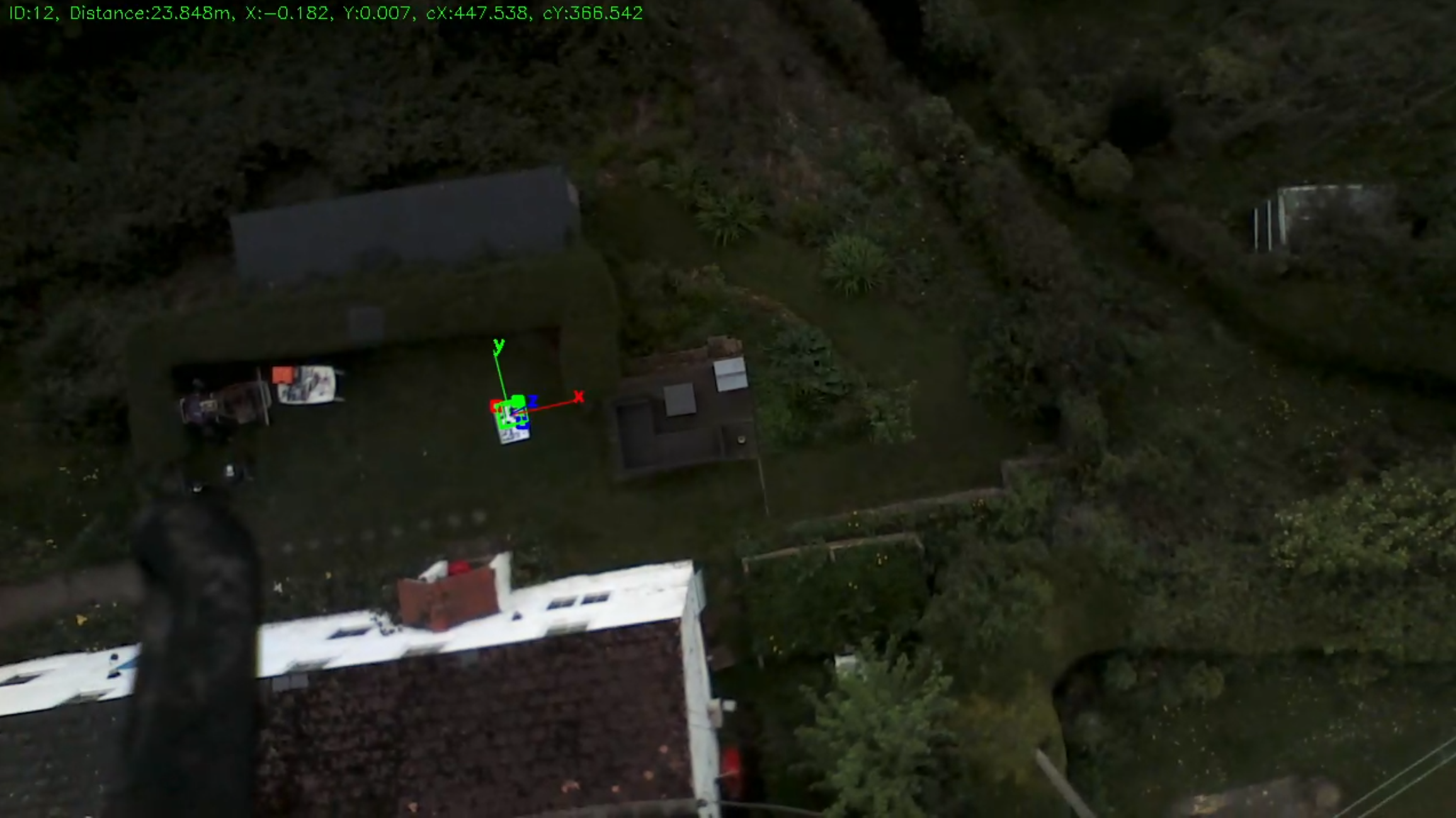
Detection altitude using 720p video
Landing marker detected and locked on at 23 meters altitude, using very poor quality 720p video. Much higher altitude can be expected using better quality camera/settings.
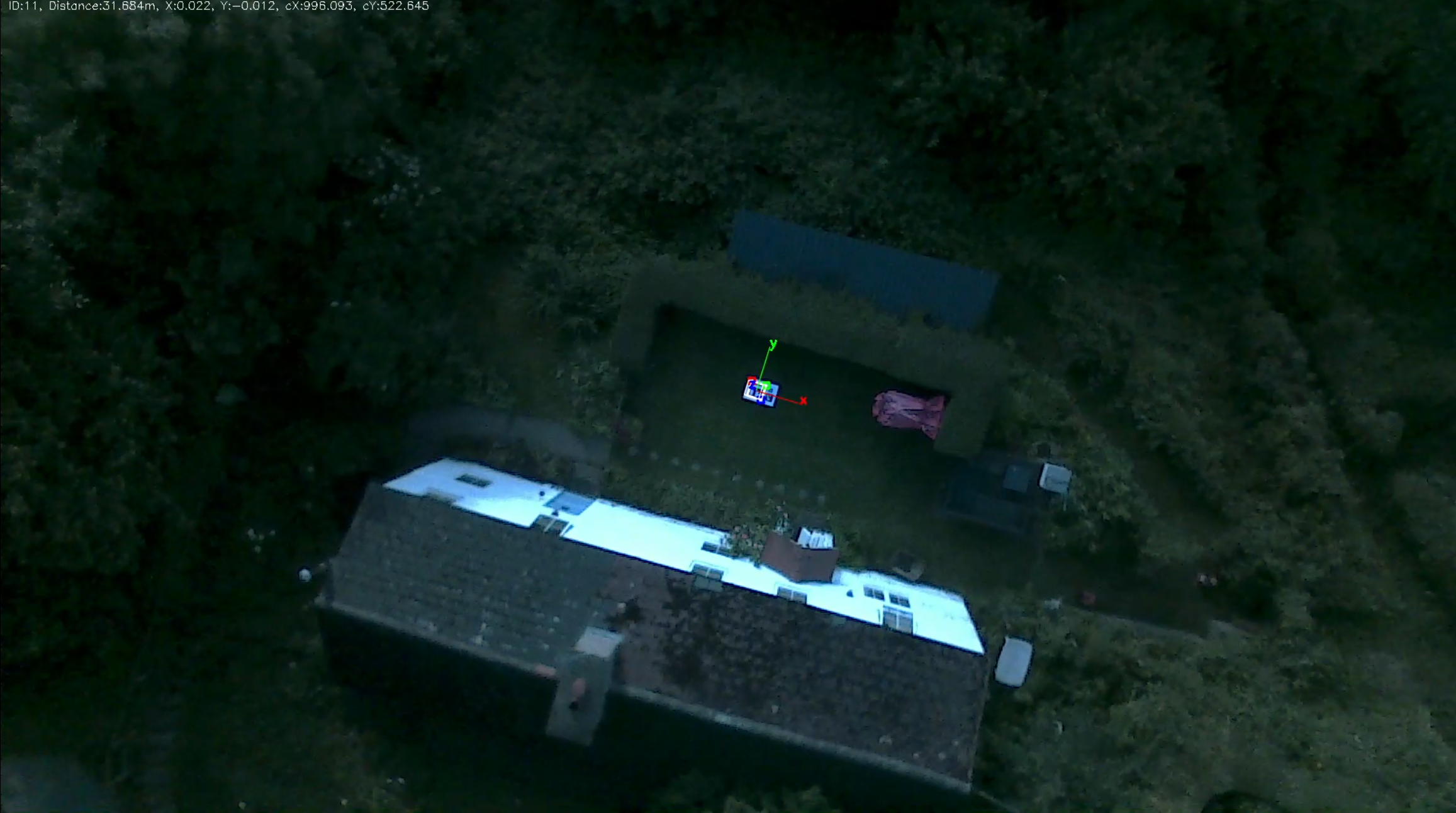
Detection altitude using 1080p video
Landing marker detected and locked on at 32 meters altitude, using very poor quality 1080p video. Much higher altitude can be expected using better quality camera/settings.
Dependencies
OpenCV (>3.0 recommended)
If possible find packages for your OS for version 3.0 or above (or install from source, for the brave), or else install 2.x packages for your OS. For debian/ubuntu which currently only has opencv2.4, you probably want to install at least these packages:
- libopencv-dev
- libopencv-calib3d-dev
- libopencv-highgui-dev
- libopencv-imgproc-dev Note that this was developed using OpenCV 3.2, although current dev/testing is under 4.0.1. SolvePNP which is the underlying function for pose estimation that aruco uses is somewhat broken in 2.4 so aruco includes it's own routines, only using solvepnp in OpenCV >3.0.
Aruco (>3.0.0)
It is recommended to install 3.1.0 from https://github.com/fnoop/aruco as it has some fixes that haven't been released yet.
Installation is straight forward:
git clone https://github.com/fnoop/aruco
git checkout 3.1.0
cd aruco
cmake . && make && sudo make install
Dronekit Install the latest dronekit:
sudo pip install dronekit
Printing Targets/Markers
The landing targets used in this project are called 'fiducial markers'. Fiducial markers are encoded objects (think QR codes or bar codes) that are used by computer vision systems as reference points in a scene. There are numerous different types of encodings, which are called 'dictionaries'. The marker library used in this project (Aruco) has its own set of dictionaries, but it also supports other dictionary types such as AprilTags.
In order to perform the recommended calibration (detailed below in the next section), it is necessary to print a specific A4 marker board:
https://github.com/goodrobots/vision_landing/blob/master/calibration/aruco_calibration_board_a4.pdf
It is important to print this on A4 size paper in exactly the size and proportions given in the PDF, as there are specific properties of the board that are expected by the calibration process.
When it comes to the landing markers themselves, the size and format depends on the nature of the craft and landing situations. The higher the craft normally flies or will start landing from, the larger the target needs to be in order to be detected. However, larger targets are more difficult to produce, transport and store, and they become unreadable at lower altitudes as they exceed the Field of View of the camera. If precision landing is acceptable from a lower altitude then a smaller target can be used. Alternatively, multiple targets can be used with varying sizes, so a larger target can be used for high altitude lock-on, then the vision system can switch to smaller targets at lower altitude for better precision and to keep within the FoV.
Aruco recommends the 'ARUCO_MIP_36h12' dictionary for the best compromise between marker size and robustness.

This is a 36bit (6x6) 250 element dictionary and the intermarker distance is smaller than other aruco dictionaries such as 16h3 (4x4), so it's possible after further testing that these dictionaries with smaller marker size are better for precision landing. Indeed, practical testing has shown that using a dictionary with a smaller grid size (and hence larger element or 'pixel' size) gives much better results from altitude. If a larger dictionary with lots of different tags is not required, then it is recommended to use a dictionary such as the AprilTags 16h5 dictionary.

So to start with, it is recommended to print a couple of markers (at your choice of size, A4 or A3 are easy to print and a good start):
https://github.com/goodrobots/vision_landing/blob/master/markers/aruco_mip_36h12_00012.png
https://github.com/goodrobots/vision_landing/blob/master/markers/aruco_mip_36h12_00036.png
Once printed, measure the size of the marker (black edge to black edge) and this is fed as the marker size parameter to vision_landing. However, note that you should either print the white border or mount the marker on a white background that leaves a white border around the black marker itself - the white border is important for reliable detection.
It is important that the markers do not deform, bend, flap or move, so it's advisable to mount them on something solid like board or perspex. Cardboard mounting up to A1 size is easy to find in local print, craft or stationary shops. It is particularly important to make sure the A4 calibration page is rigid when doing the calibration.
In order to address the problem of large markers exceeding the camera FoV at lower altitudes, multiple markers of differing sizes can be used. As the craft descends in altitude locked on to a large marker, at some point a smaller marker will come into view and can be locked on to. Marker boards can be used for increased robustness and accuracy. An example of such a multiple marker board is included as an A1 PDF:
https://github.com/goodrobots/vision_landing/blob/master/markers/a1-landing.pdf

After testing and experimentation, it was found to have less markers as close together as possible in a circular pattern, with small pattern grids and larger intermarker distances gave better results. An updated marker board as below is preset as default in the config file:
https://github.com/goodrobots/vision_landing/blob/master/markers/april16h5-landing-a1.pdf

Also during development and testing, it was found that as the smaller markers come into view, the detection bounces between the two which can cause oscillations or other unexpected (and undesirable!) behaviour of the UAV. A configurable filter that helps to debounce the detection thresholds has been implemented and can be set in the config:
## Marker tracking history - number of frames that each marker is tracked for active marker transition
markerhistory=30
## Marker tracking threshold - percentage of frames in tracking history that marker must be detected to be activated
markerthreshold=80
The above settings mean that a 30 frame marker buffer is used (equal to 1 second at 30fps), and that of the last 30 frames, the smaller marker must be accurately detected in at least 80% of those 30 frames before vision_landing will lock on to that new smaller marker. This greatly helps when landing on a pattern of concentric diminishing markers.
Camera Calibration
In order to perform any accurate Computer Vision work, you must first calibrate your camera. Every camera and lens combination has different focal lengths, field of view, aperture, sensor size, optical center and lens distortions (eg. fisheye also known as positive radial distortion, or barrel distortion). Even cameras or lenses of the same make/model will have small manufacturing tolerance/mistakes. All of these must be known and compensated for.
OpenCV (which is what the vision code in this project uses) uses optional 'Camera Matrix' and 'Distortion Coefficients' matrices (collectively called intrinsics) which are used to 'undistort' the raw image for accurate further processing and can also be used to automatically calculate focal length and field of view, necessary in turn to calculate the target angular offsets for precision landing and pose estimation used for accurate distance measurements. There are numerous calibration methods for opencv, but there is a simple interactive routine included in the Aruco software installed as a dependency, so that process is recommended and documented briefly here:
- Print the A4 calibration board detailed above
- Run aruco_calibration program:
aruco_calibration live mycamera_calibration.yml -m <vision_landing_dir>/calibration/aruco_calibration_board_a4.yml -size 0.033 - Move the calibration board so it's in every position of the screen, particularly the outer edges (this is very important to capture the distortion of the lens at it's most extreme) and press 's' to capture a calibration snapshot at each position.
- After taking enough snapshots (more the better, at least 10 is good), press 'c' to produce the calibration. With the above command, it will produce a 'mycamera_calibration.yml'
Installation
First ensure the above dependencies are already installed.
There are two main components:
- vision_landing, a python script
- track_targets, a c++ program
track_targets must be compiled and installed into the main directory before vision_landing can be run. vision_landing calls track_targets to do the actual target detection and vector calculations.
git clone https://github.com/goodrobots/vision_landing
cd vision_landing/src
cmake . && make && make install
You should now have a track_targets file in the same directory as the vision_landing script (the root of the vision_landing project).
Service Installation
In order to provide startup at system boot and 'graceful' stop, a systemd manifest is provided (vision_landing.service). To install, either alter the manifest with the full path to where vision_landing has been downloaded to (replace all instances of /usr/local/vision_landing with new path), or perhaps easier is to copy or symlink the directory to /usr/local and the provided manifest can be used without alteration. The following should be executed from the root of vision_landing project (ie. in the same directory as the vision_landing script and track_targets after install):
sudo ln -s `pwd` /usr/local
sudo cp vision_landing.service /etc/systemd/system
sudo systemctl daemon-reload
Maverick - Automated Installation
The Maverick project pre-installs everything necessary for vision_landing. Flash-able OS images are available for multiple platforms. To start vision_landing, ensure anything else that is using the camera is stopped, and simply use:
maverick start vision_landing
Running
To run this project, you MUST have accurate calibration data for your camera sensor/lens combination. This can be quite challenging to accomplish, so sample calibration data for Odroid oCam 5cr and Raspberry Pi cameras (v1 only) are included in the calibration directory. More will hopefully be added in the future. Note that even these supplied calibrations will not necessarily be perfect or even be guaranteed to work for your particular camera/lens combination, even if they are the same model. It is highly recommended to take 10 minutes to perform the calibration.
Systemd running
Systemd is the recommended way to run vision_landing, and assumes that the 'Recommended Installation' in the previous section has been completed. Using systemd, starting vision_landing is as simple as executing:
sudo systemctl start vision_landing
It can be stopped by executing:
sudo systemctl stop vision_landing
Note that when using systemd for control, mandatory and optional parameters are set using vision_landing.conf.
Manual running
vision_landing can also be run without systemd by just calling the main script and relying on the config file for correct configuration, or calling with the necessary mandatory and optional parameters. It is highly recommended to use the config file for ease of use and minimum confusion.
Examples
./vision_landing # (uses values in vision_landing.conf)
./vision_landing --input /dev/ttyS0 --markersize 0.235 --calibration calibration/ocam5cr-calibration-640x480.yml
./vision_landing --markerid 580 --markerdict TAG36h11 --input /dev/ttyS0 0.235 --calibration calibration/ocam5cr-calibration-640x480.yml
./vision_landing --simulator --input /dev/video2 --output "appsrc ! autovideoconvert ! v4l2video11h264enc ! h264parse ! rtph264pay config-interval=1 pt=96 ! udpsink host=192.168.1.70 port=5000 sync=false" --markerdict TAG36h11 --input tcp:localhost:5777 --markersize 0.235 --calibration calibration/ocam5cr-calibration-640x480.yml
./vision_landing --input /dev/video2 --output /srv/maverick/data/video/landing.mpg --markerdict TAG36h11 --input tcp:localhost:5777 --markersize 0.235 --width 1280 --height 720 --calibration calibration/ocam5cr-calibration-1280x720.yml
Mandatory parameters
- connect: This is the dronekit connection string, eg. /dev/ttyS0 (for serial connection to FC), tcp:localhost:5770 (tcp connection to mavproxy), udp:localhost:14560 (udp connection to mavproxy).
- markersize: This is the size of the fiducial marker in meters. So a typical april tag printed on A3 will be around 23.5cm from black edge to black edge, so the value here would be 0.235.
- calibration: This is the file containing calibration data, eg. calibration/ocam5cr-calibration-640x480.yml
Optional parameters
** Note that the --fakerangefinder flag is needed unless you have a proper laser rangefinder or running arducopter >3.5-rc2 **
- --input: This is the video stream 'pipeline' used to look for targets. It defaults to /dev/video0 which is what most USB cameras show up as (/dev/video2 typically for odroid xu4 with hardware encoding activated). Video files can be used for testing by just specifying the video file name here. A gstreamer pipeline can also be used here as long as it ends in appsink (eg. v4l2src device=/dev/video2 ! decodebin ! videoconvert ! appsink)
-
--output: This is the output 'pipeline' that can be used to save the video stream with AR data overlaid. This can either be a video file name (which will be uncompressed and very large), or you can create gstreamer pipelines. Example pipeline for odroid xu4 with hardware encoding activated to stream h264 compressed video with AR markers in realtime would be (note gstreamer pipeline must start with appsrc):
appsrc ! autovideoconvert ! v4l2video11h264enc ! h264parse ! rtph264pay config-interval=1 pt=96 ! udpsink host=192.168.1.x port=5000 sync=false - --markerid: Specify a marker ID to detect. If specified, only a target matching this ID will be used for landing and any other target will be rejected. If not specified, all targets in the specified or default dictionary will be detected and the closest will be chosen for landing.
- --markerdict: Type of marker dictionary to use. Only one dictionary can be detected at any one time. Supported dictionaries are: ARUCO ARUCO_MIP_16h3 ARUCO_MIP_25h7 ARUCO_MIP_36h12 ARTOOLKITPLUS ARTOOLKITPLUSBCH TAG16h5 TAG25h7 TAG25h9 TAG36h11 TAG36h10. Defaults to ARUCO_MIP_36h12.
- --simulator: If this flag is set, when the dronekit connection is made the script will wait for prearm checks to pass and then take off to preset altitude and then initiate landing. This is typically used when connecting to SITL simulator to test precision landing.
- --width: Set the width of the incoming video stream. Note that camera intrinsics are resized but this will only work if the area of camera is sensor is the same as the calibration. If a different aspect ratio is used then an appropriate calibration should be used, ie. 1280x720 resolution will not work with 640x480 calibration data.
- --height: As width, but for height.
- --fps: This attempts to set frames per second of incoming video but this is often not supported by the camera driver. It can be used as a 'fudge factor' if saved video files look too fast or slow.
- --brightness: This can be used to increase or decrease gain or brightness in high or low light conditions.
- --fakerangefinder: This flag tells vision_landing to also send fake rangefinder data based on distance detected from a selected target. This is necessary for arducopter firmware <3.5-rc2.
- --verbose: Turn on some extra info/debug output
Intel RealSense enhancements
The realsense branch of this project adds some enhancements when using an Intel RealSense camera. These units actually have three cameras inside - a color RGB camera, two near-InfraRed cameras, and they also have a laser projector for throwing IR patterns onto flat surfaces that are otherwise hard to map. From the two infrared cameras, a depth map is calculated. All of this is done in custom ASIC hardware on the unit so no additional processing is necessary on the host computer. In addition, the units are factory calibrated and intrinsic calibration data is automatically available for each individual unit through the librealsense library/api. They are an excellent, cheap option for obtaining stereo depth data.
However, for the purposes of vision_landing they have advantages and disadvantages. On the downside, the cameras are very low quality mobile-pinhole type lenses/sensors. They are configured by default for indoor use, and configuring them for outdoor use is tricky. In particular, the color RGB camera is very poor and is terrible at high contrasting colours - unfortunately exactly what the landing markers are - the white bleeds onto the black and makes detection difficult and unreliable. On the upside, the two IR cameras are global shutter and high framerate (up to 90fps). This makes them actually very good for Computer Vision, and excellent results can be obtained using these cameras. It seems that the toner of laser printers absorb IR very well, so targets printed on a laser printer have excellent contrast to the IR cameras and are very clear from altitude. In addition, the streams from the three cameras can be read simultaneously, as well as the synthetic streams for depth, and corrected and synchronised streams between the cameras. This means we can use the IR camera for the marker detection and estimation, and use either the color stream or depth mapping for visualisation.
