Split Flap Save
code for split-flap display
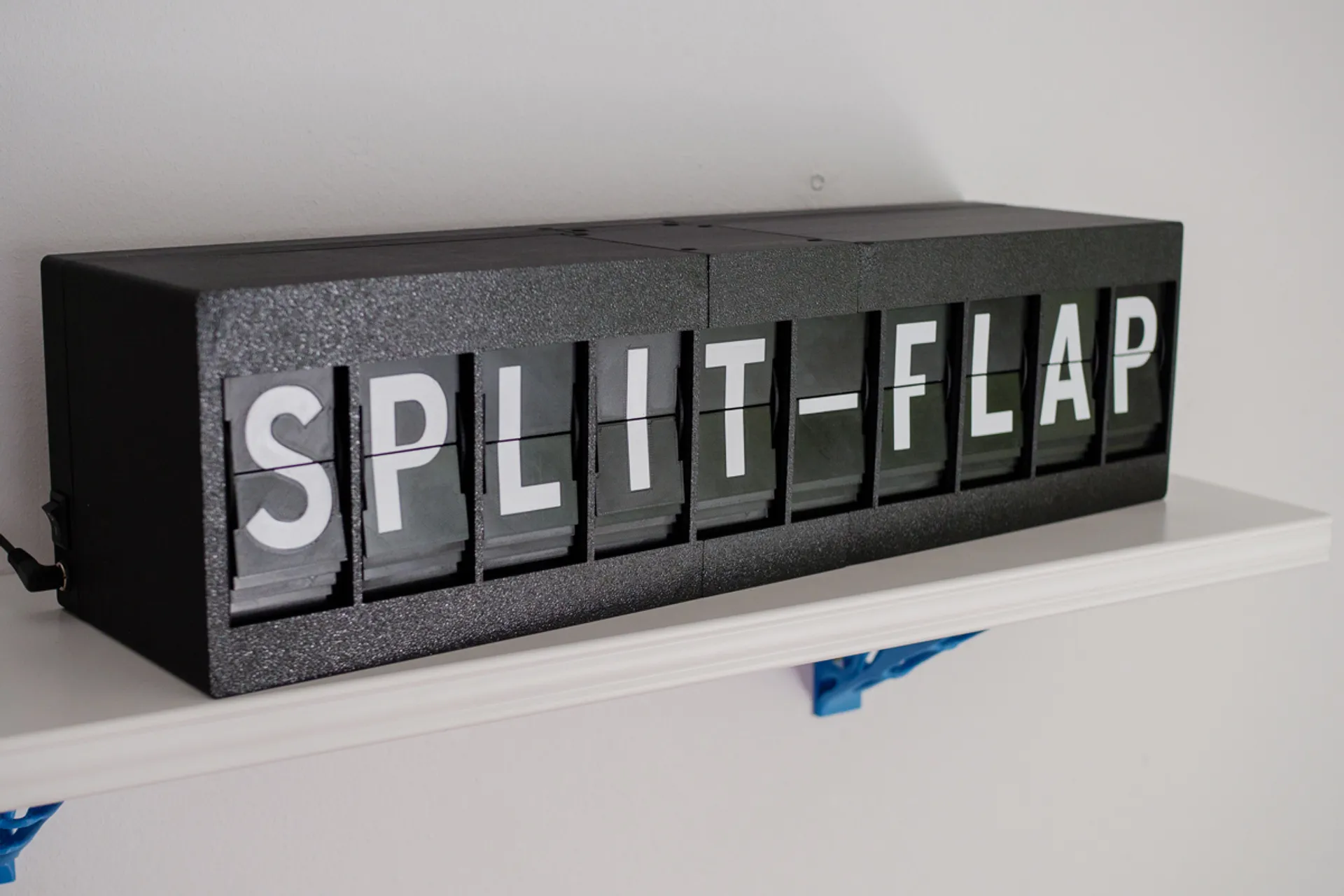
Split-Flap
 3D-files here: https://www.prusaprinters.org/prints/69464-split-flap-display
Notable Forks
As I'm not actively maintaining and developing the code further, here are some forks:
- https://github.com/JonnyBooker/split-flap
- https://github.com/codingcatgirl/split-flap-fae-pcb (improved PCB, drop-in replacement)
General
The display's electronics use one esp01 as the master and up to 16 arduinos as slaves. The esp handles the webinterface and communicates to the units via I2C. Each unit is resposible for setting the zero position of the drum on startup and displaying any letter the master send its way.
Assemble everything according to the instruction manual.
PCB
Gerber files are in the pcb folder. You need one per unit. Populate components according to the instruction manual on prusaprinters.
Unit
Each split-flap unit consists of an arduino nano mounted on a custom pcb. It controls a 28BYJ-48 stepper motor via a ULN2003 driver chip. The drum with the flaps is homed with a KY003 hall sensor and a magnet mounted to the drum.
Upload the arduino sketch "unit.ino" in the unit folder to each unit's arduino nano. Before that set the offset with the "eeprom write offset" sketch.
set zero position offset
The zero position (or blank flaps position in this case) is attained by driving the stepper to the hall sensor and step a few steps forward. This offset is individual to every unit and needs to be saved to the arduino nano's EEPROM.
I wrote a simple sketch to set the offset. Upload the "EEPROM_Write_Offset.ino" sketch and open the serial monitor with 115200 baudrate. It will tell you the current offset and you can enter a new offset. It should be around 100. You may need to upload the "unit.ino" sketch and see if the offset is correct. Repeat until the blank flap is showing every time the unit homes.
set unit address
Every units address is set by a DIP switch. They need to be set ascending from zero in binary. This is how my 10 units are set, 1 means switch is in the up-position:
| Unit 1 | Unit 2 | Unit 3 | Unit 4 | Unit 5 | Unit 6 | Unit 7 | Unit 8 | Unit 9 | Unit 10 |
|---|---|---|---|---|---|---|---|---|---|
| 0000 | 0001 | 0010 | 0011 | 0100 | 0101 | 0110 | 0111 | 1000 | 1001 |
ESP01
To upload the sketch to the ESP01 you need to install a few things to your arduino IDE.
- Install the esp8266 board to your Arduino IDE https://randomnerdtutorials.com/how-to-install-esp8266-board-arduino-ide/
- Install the arduino esp8266 littleFS plugin to use the file system of the ESP01, you can follow this tutorial: https://randomnerdtutorials.com/install-esp8266-nodemcu-littlefs-arduino/
- Install the following libraries:
- ESPAsyncWebServer https://github.com/me-no-dev/ESPAsyncWebServer/archive/master.zip
- ESPAsyncTCP https://github.com/me-no-dev/ESPAsyncTCP/archive/master.zip
- Arduino_JSON from the library manager
- NTPClient from the library manager
- ezTime from the library manager
To upload sketches to the ESP01 you can either use an Arduino https://create.arduino.cc/projecthub/pratikdesai/how-to-program-esp8266-esp-01-module-with-arduino-uno-598166 or you can buy a dedicated programmer. I highly recommend getting a programmer as it makes uploading programs onto the ESP01 much faster.
Open the sketch "ESPMaster.ino" in the ESPMaster folder, change your board to "Generic ESP8266 Module", choose the correct COM-port and click Tools->ESP8266 LittleFS Data Upload. This uploads the website onto the ESP01's file system.
change sketch values
Modify the sketch where it says
// REPLACE WITH YOUR NETWORK CREDENTIALS const char* ssid = "SSID"; const char* password = "12345678901234567890";
and insert your network's credentials.
Also change the timezoneString to your time zone. You can find the TZ database names here: https://en.wikipedia.org/wiki/List_of_tz_database_time_zones
You can also modify the date and clock format easily by using this table: https://github.com/ropg/ezTime#datetime
final upload
Now you only need to upload the sketch and you are done. Stick the ESP01 onto the first unit's PCB and navigate to the IP-address the ESP01 is getting assigned from your router.
common mistakes
If the ESP is not talking to the units correctly, check the UNITSAMOUNT in the ESPMaster.ino. The amount of units connected has to match.
