Spiki Save
A spiral inductor footprint generator for Kicad
spiki - spirals for KiCad
a simple application to generate a KiCad footprint (module) for spiral inductors on the PCB.
To run it you will need
- PyQt, used for the GUI
-
fasthenry, used to compute the actual inductance
Source code for an updated fasthenry version can be downloaded from Whiteley Research Inc., at http://wrcad.com/ftp/pub/fasthenry-3.0wr-110915.tar.gz
A Windows executable is also available there, at http://wrcad.com/ftp/pub/fasthenry-3.0wr-092815-setup.exe - NLopt, to find the inductor dimensions (spacing only, currently) to obtain a defined inductance value
The fasthenry executable needs to be in the path (or in the same directory as spiki.py)
How to use it
The GUI has just a single window, where all the relevant parameters are entered:

Inductor parameters
- number of turns : also partial turns (e.g. 3.5) are accepted and sometimes useful to position the terminals at a convenient angle
- inner radius : distance of the spiral starting point from the center
- pitch : distance between the center line of two adjacent turns
- spacing : spacing between two adjacent turns.
Pitch and spacing above are of course related and changing one changes automatically the other - trace width : width of the conductor trace. Changing this force a change in the spacing to keep the pitch constant
- number of layers : number of layer used for the spiral trace. At present only 1 and 2 are supported
- estimated inductance : inductance estimated by a closed-form formula. For 1-layer inductor the estimate is usually good, for 2-layers can be quite off
PCB properties
- PCB thickness : needed for 2-layer inductors
- copper thickness : trace thickness, used to compute the inductor resistance and, indirectly, its merit factor Q
- min spacing
Settings
- drawing tolerance : maximum deviation from the ideal spiral shape; the spirals are approximated with straight segments
- inductor style : at present only circular is supported
Simulation
- frequency : used to compute the actual inductance and losses
- skin depth : for info, to compare with the trace width and thickness
- inductance : value obtained from the simulation
- resistance : value obtained from the simulation
- Q : the ratio between the inductive reactance and the resistance, at the simulation frequency
Pressing the Run simulation button starts the fasthenry program in the background. While the program is running, the message Simulating... is shown in the status bar at the bottom
- desired inductance : used for the optimization. The spacing will be adjusted to obtain this value of inductance, at the frequency specified above
Pressing the optimize button runs the fasthenry program in the background, changing the inductor traces spacing until the desired inductance value is obtained. Requires the NLopt library with Python bindings to be installed.
Once a spiral inductor with the desired characteristics has been obtained, the corresponding KiCad footprint can be saved to a file by using the top menu (File -> Save module)
Examples
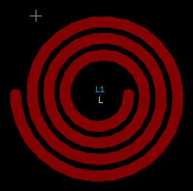
Here are some pictures of spiral inductors generated with spiki
- 3.5 turn, single- layer
- 3.5 turn, two layers

