PSAVanCanBridge Save
VAN - CAN protocol bridge (V2C) for cars made by PSA Group (Peugeot, Citroen)
PSA VAN-CAN protocol bridge
What is it ?
In the beginning of 2000's the PSA group (Peugeot and Citroen) used VAN bus as a communication protocol between the various comfort-related equipment. Later around 2005 they started to replace this protocol in their newer cars with the CAN bus protocol, however some cars had VAN bus inside them until 2009.
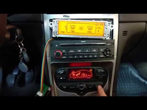
The goal of this project is to have the new peripherals (mainly the head unit and the multi function display) using the CAN bus protocol working inside cars utilizing VAN bus.
Why ?
Because it is fun. But other than that I wanted to replace the head unit of my car with another one which supports playing MP3 and also supports the original remote stalk behind the steering wheel. I also wanted to have the new shiny display working in my car from newer models. If you are interested, you can read the whole story behind the development at the History section in the wiki.
Components
The components needed for the project to work in your car is the following:
- Head unit (RD4/RD43/RD45)
- Multifunction display
- ISO-Quadlock-Display-JST XH6 conversion cable (see more info in the wiki)
- ISO-fakra aerial antenna converter
- PSA VAN-CAN protocol bridge hardware
I built a "shield" for the ESP32 dev board where I integrated the CAN bus transceivers and the TSS463C VAN controller onto one board. The KiCad project files can be found in this repository.

Liability
I used the software in my car for months, without any sign of errors. However I cannot take any responsibility if something goes wrong if you build it and install it in your car. So use the software and hardware at your own risk.
Functionality
I implemented the functions which came with the original V2C boards (see what are those in the history section in the wiki), and even more! I created a video which demonstrates most of the functionality:
But here is the list of the bridged functions:
- Head unit support: RD4/RD43/RD45
- Radio remote stalk support
- VIN bridging for the anti-theft functionality of the RD4/RD43/RD45 head units
- Speed and RPM (for automatic volume correction functionality in the head unit)
- Messages shown on the multifunction display (MFD)
- Air conditioning status (speed, air recycling, rear window demist, A/C enabled status also the internal temperature, and the directions are read via diagnostic messages)
- Most of the odometer functionality (fuel level, coolant temperature, lights and turn-indicator status, mil, airbag lights, only the battery and the heating spark indicator is missing)
- Display and radio lights based on the side lights and dipped beam status
- Trip computer related data
- Door statuses
- Outside temperature
- Economy mode warning
- Seatbelt warning (if the vehicle speed is above 10km/h)
- Display the remaining fuel in percentage
- Display the remaining fuel in liters
- Display the oil temperature
- Semi-automatic VIN coding for the headunit to stop beeping (anti theft protection)
Removing the old display from the car
If you remove the original display from the car the trip computer related data, the door statuses, and the digital air conditioning system may stop working. In the 307 the VAN data wires for the A/C are routed through the display. So obviously if you remove the display the circuit will be broken, which is pretty easy to fix. You just need to create two shortcuts on the original connector (4-5 DATA pins and 17-18 DATAB pins).

The reason behind the missing functionality is due to the fact that the display queries the BSI for the trip computer data, and the door statuses. If you would like to remove the original display from your car you need to build a hardware revision which contains a TSS463C.
Head unit anti-theft protection
In cars made by PSA the the head unit contains the VIN number. The BSI sends it's VIN on the CAN bus. If the head unit detects a mismatch between the VIN coded inside it and the VIN received on the CAN bus then signals it with a beeping every few seconds. To prevent this you need to configure the VIN coded into your head unit in the config.h file. If you don't know the VIN inside your head unit then you can do it via the following semi-automatic method. You only need to do this once as the device stores the correct VIN number for the radio.
- Turn on the radio (source should be tuner)
- Switch to AM band and set it to 545 kHz (if you have an RD45) or 543 kHz (if you have an RD4 or RD43)

- Press the Menu button on the radio (you should see this menu). It doesn't matter which item is selected.

- Press the following combination with the arrows on your radio:
Left-Right-Left-Right (almost like the Konami code :smiley:)
If you mistype the combination, then exit the menu, and return to it again.

- Now the beeping should stop
Compatibility
The software was tested on a Peugeot 307 SW made in 2004 however most probably it is compatible with all of the cars with VAN bus made by the PSA group. Here is a short list about the cars which should be compatible:
- Peugeot 206 multiplexed (MUX) versions (2001.09 - )
- Peugeot 206+
- Peugeot 307 (2001-2005 first quarter)
- Peugeot 406 (2000-)
- Peugeot 1007 (2005-2007)
- Peugeot Partner
- Citroen C2
- Citroen C3 (2001-2005)
- Citroen C5 (2001-2005)
- Citroen C8 (2001-2005)
- Citroen Berlingo
- Citroen Xsara/Picasso
- EuroVan2 (Peugeot 807,Citroen C8, Fiat Ulysse, Lancia Phedra)
Installation
The easiest place to install the hardware in a car is the connectors of the original head unit. Below you can see the schematics of a patch lead which converts the ISO connector to Quadlock type and exposes the VAN and CAN data pins to a JST XH 6 connector where you can connect the PSA VAN-CAN bridge hardware.

Project structure
I tried to keep things as simple as possible but I wanted to create code where everything has its own place. So there are a lot of files. I am not that happy with the idea of having separate .h an .cpp files so I have implementations inside the header files. I know that this may not be a best practice but this approach helped me to avoid having 50 or more additional files.
The main sketch file is the PSAVanCanBridgeMain.cpp file. In the Config.h file you can find some variables which you might want to change based on which hardware you built.
Every VAN bus message has its own descriptor file. They can be found inside the src/van/structs folder. This file contains the message identifier, and the description of the bytes which build the actual array floating around the bus.
The messages on the CAN bus also has these kind of descriptor files. They can be found inside the src/can/structs folder. These files help to build the messages in a way that the code remains more readable.
To convert these files to the actual byte array which will be received or sent on the wire there is a helper template class which can be found inside the src/helpers/serializer.h file.
In order to avoid cluttering the main sketch with the message conversions every VAN and CAN bus related message processor has a handler file. They can be found inside the Handlers folder under the corresponding protocols directory. The VAN bus related handler files derive from an abstract class which can be found inside the AbstractVanMessageHandler.h. The CAN bus related handlers derive from the CanMessageHandlerBase class.
Building the project
From Arduino
Follow these steps to build the project:
- Install the ESP32 boards into the Arduino IDE (follow the instructions here)
- Install the libraries from the Used libraries section
- They should be installed under your documents folder. Which should be something like this:
- C:\Users\YOUR_NAME\Documents\Arduino\libraries
- At the end you should have a folder structure similar to this:
- C:\Users\YOUR_NAME\Documents\Arduino\libraries\esp32_arduino_rmt_van_rx\
- C:\Users\YOUR_NAME\Documents\Arduino\libraries\tss463_van\
- C:\Users\YOUR_NAME\Documents\Arduino\libraries\Queue\
- They should be installed under your documents folder. Which should be something like this:
- Extract the contents of the zip file
- Open the empty PSAVanCanBridge\PSAVanCanBridge.ino file from the Arduino IDE (do not rename any file or whatsoever)
- Select ESP32 Dev module from Tools\Board menu
- Now you should be able to compile it by clicking on the menu Sketch\Verify/Compile
From PlatformIO
You can also open the project from PlatformIO. It will download the necessary libraries so you don't have to worry about them.
Used libraries
- Arduino abstract serial (you don't need to install this one as the required files are included in the src/SerialPort folder)
- ESP32 RMT peripheral VAN bus reader (can be installed from the library manager from the Arduino IDE)
- TSS463C VAN interface library (can be installed from the library manager from the Arduino IDE)
- [Arduino Library for the ESP32 CAN Bus][lib_esp32_can]
- Queue
