PicoADK Hardware Save
A RP2040 based Audio Development Kit with 32 Bit Audio Output. Build your own standalone synthesizers!
Chaos Communication Camp 2023 News
Update: You can still get your PicoADKs from our Webshop. The generative synthesizer code will be released in the next days after cleanup and improvements.
The binary firmware with the generative synth can be found here. Update: More firmware can be found here
Update
Harvard University Electronic Instrument Design Lab has prepared a Wiki with examples for the PicoADK. Check it out here.
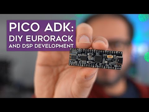
PicoADK - Pico Audio Development Kit

Introduction
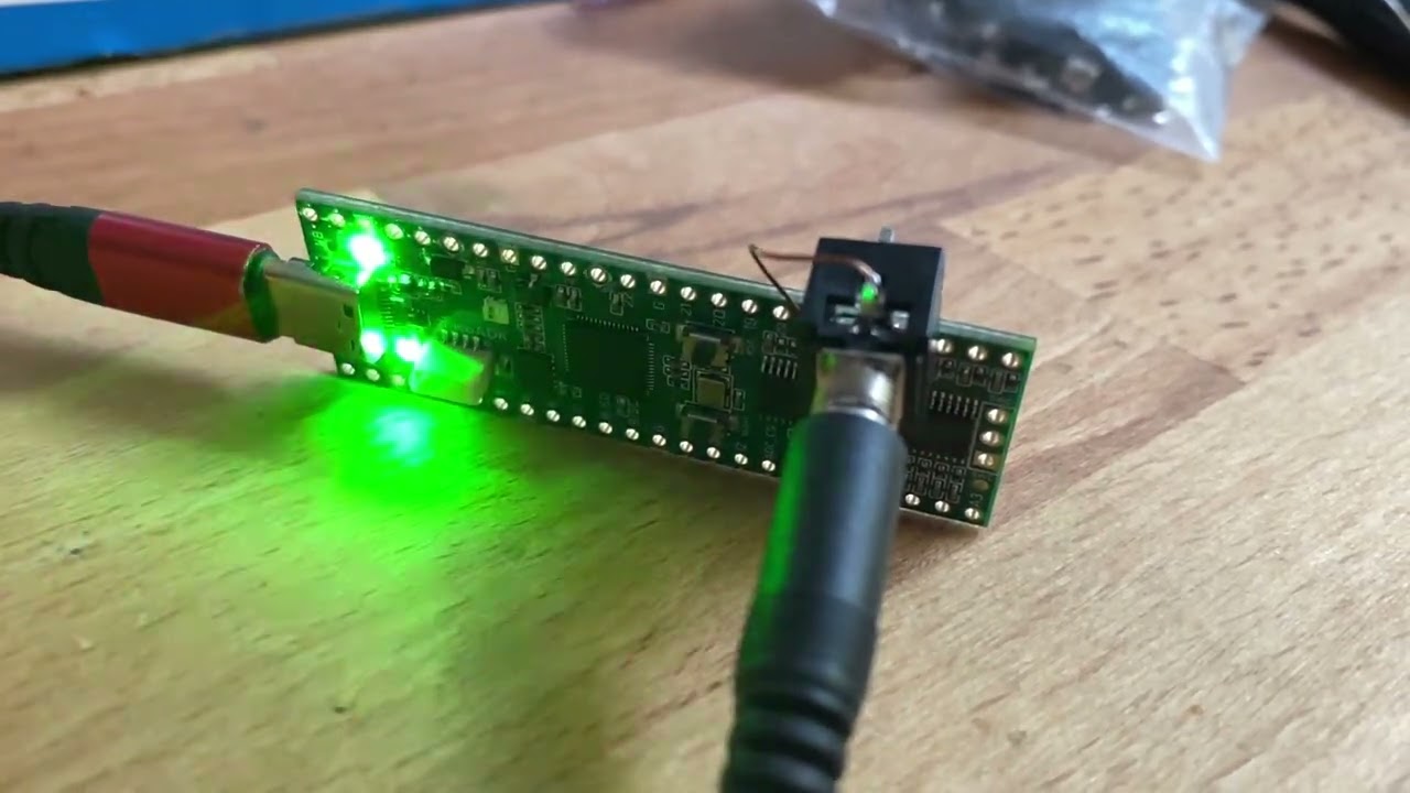
The PicoADK is a RP2040 based Audio Development Board, which allows you to build your own digital oscillators, synthesizers, noise boxes and experiment around. It has all the base features of the Raspberry Pico, plus a high quality Audio Output, 8 Analog Inputs for connecting potentiometers, control voltage from eurorack systems or even additional input signals.
Even though it is very small, it is capable of synthesizing and outputting a very high quality sound output. Thanks to the Vult DSP language you can even create digital filters, waveshapers, oscillators and even complete synthesizers!
Sound demos
You can find some sound teasers at Soundcloud.
Buy
The PicoADK can be ordered at Schneidersladen and Datanoise Shop.
Specifications
- RP2040 Dual Core Cortex M0+ running at up to 400MHz (overclocked)
- USB Type-C connector (Host & Device Mode)
- 2MB Flash for Firmware and Data (4MB on v1.1b)
- Very low noise LDO regulators with separate LDO for digital circuits and separate for analog circuits, no switching regulators
- Partially pin-compatible with RP2040 (besides a few pins internally used or rearranged), extra 4 pins on each side for SPI ADC
- Audio DAC PCM5100A, up to 32-bit high-quality output
- Dedicated Boot and Reset Buttons
- 8 channel 12-bit ADC with up to 1MS/s, with selectable 3.3V range (on-board low-noise power supply) or range up to 5V via external VREF
- Low-Pass filter on each ADC input with external 5V voltage reference input suitable for CV (no overvoltage protection, unipolar)
- Symbols marking special pin functions on the pin headers
- 4 LEDs on shared GPIO2-5 for debugging, 1 RGB WS2812B LED
- ESD Protection on USB
- SWD Debug Header
- JST 1.0mm 4 Pin (QWIIC compatible) I2C Connector
Firmware
You can find the firmware template including examples at https://github.com/DatanoiseTV/PicoADK-Firmware-Template
The repository contains the I2S codec drivers, A custom build step for Vult DSP based projects and a synthesizer as an example and should be a good starting point for most projects.
Pinout (PicoADK v1.1) - 48 Pin

The Analog Lineout are the Pins marked with L and R. You can find them on the right bottom of the PicoADK (when USB is facing upwards).
Interactive pinout at https://datanoise.net/picoadk/
Internal Signals
Some signals are routed to internal peripherals as following:
| GPIO | Function | Shared w/ Header? |
|---|---|---|
| GPIO2 | Debug LED 1 | yes |
| GPIO3 | Debug LED 2 | yes |
| GPIO4 | Debug LED 3 | yes |
| GPIO5 | Debug LED 4 | yes |
| GPIO10 | ADC128 SPI1 SCK | yes |
| GPIO11 | ADC128 SPI1 MOSI | yes |
| GPIO12 | ADC128 SPI1 MISO | yes |
| GPIO13 | ADC128 SPI1 CSn | yes |
| GPIO15 | Big Debug LED (WS2812 on v1.1a) | no |
| GPIO16 | PCM5100A I2S DAT | no |
| GPIO17 | PCM5100A I2S BCLK | no |
| GPIO18 | PCM5100A I2S LRCLK | no |
| GPIO23 | PCM5100A DEMP | no |
| GPIO24 | VBUS Detect Pin | no |
| GPIO25 | PCM5102 XSMT | no |
The SPI ADC shares the GPIO10 to GPIO13, which are also present on the pin headers. Please be aware of that.
Make sure your software controls the XSMT and DEMP pins. The XSMT needs to be controled by the software to mute/unmute the audio output. With the DEMP pin you can control the Deemphasis for 44100 Hz.
Changes required for 5V ADC range (default is 3.3v)
By default, the ADC range is approximately 0-3.3v provided by a low-noise internal 3.3V voltage source. If you want to use 0-5V input range, you need to cut the trace on the jumper on the bottom of the PCB and bridge the VEXT position with the middle of the jumper. MAKE SURE THAT YOU CHECK FOR NON-CONTINUITY WITH A MULTIMETER between the 3.3V reference side and the middle of the jumper to make sure you've cut the bridge properly. The recommended way of cutting the trace is using a sharp blade such as an exacto knife. Use of a dremel or similar is NOT recommended, as it could damage the inner layers of the board
First Flashing / Getting started
- Press and Hold the B(OOT) button and press reset quickly. Afterwards release the BOOT button and you will see a RP2_BOOT drive on your computer. After that, you will be able to just drag and drop the UF2 file with the firmware image onto it.
Arduino IDE support
The PicoADK is supported by Arduino using the Arduino Pico Package from Earle Philhower https://github.com/earlephilhower/arduino-pico
The Arduino support is currently experimental and the recommended software template is to use this repository. The PicoADK board is supported on Arduino Pico Release 2.6.4+ onwards.
Micropython support
Update: As of CircuitPython 8.2.1, the PicoADK is supported! Get it here
Projects
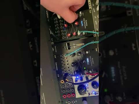
- PicoADK Eurorack Module (by Datanoise)
Want your project listed? Let me know.
Community
You can find the PicoADK at Discord right here and a community discussion board on GitHub Discussions
EDA Libraries
3D Model
The STEP file for mechanical design can be found here.
More Pictures
 Photo courtesy of Paul D. Pape - derwellenreiter for schneidersladen, Berlin, Germany.
 Photo courtesy of Paul D. Pape - derwellenreiter for schneidersladen, Berlin, Germany.

