LoRa E5 Breakout Save
LoRa-E5 Breakout board
LoRa-E5 breakout board

Mainly based on LoRa-E5 mini board from Seedstudio, but since it was out of stock and I needed some specific wiring, I designed my own based on the Open Source design they made (thank for sharing)
I'm using mainly to flash custom firmware in it, and not using AT default firmware.
These boards have been received, assembled, and works as expected
- LoRa-E5 Module
- No USB/Serial, SMD FTDI 6 pins connector (use 3.3V FTDI One, not 5V)
- Exposed JTAG pins needed to flash module (PA13-SWDIO / PA14-SWCLK / RESET)
- Green Led on PB10
- Red Led on PB5
- Optional 2 Tactile Switch (boot and reset)
- 2 Antenna connector (u-Fl and SMA), select with 0 Ohm resistor
- I2C 4 pins location for "classic" sensors
Detailed Description
No specific documentation for now, it's just a kind of wiring helper as schematic.
I also assume that you are familiar with all LoRaWAN stuff, all setup/infrastructure/network server/provisionning and other are out of scope of this repository.
Schematics

Boards
You can order PCBs of this board at [PCBs.io][3]
PCBs.io give me some reward when you order my designed boards from their site. This is pretty good, because I can use these rewards to create and design new boards and order boards for a discounted price, so if you don't care about PCB manufacturer please use PCBs.io.
Looks like PCBs.io is gone, I do not have any rewards from PCBs.io since August 2020 and my free order placed after are still not received, so my guess they are not on business anymore.
So you can order the board on oshpark.
It's a pitty after several discuss with OSHPark that I can't have any rewards for each people ordering my boards, this would allow me to order free PCB for shared projects and create new ones. For information my shared boards generated a total of $285 162.00 orders at PCBs.io in 4 years, not bad at all :-)
Hoping one day OSHparks will thanks me giving them this market.
Assembled boards
Top & bottom side V1.0

Bill Of Material
Nothing fancy, all components are 0805 and/or PTH and can be ordered almost anywhere (digikey, mouser, radiospare, ...). use only what you need dependings on what you want to do.
Check Seeed format BOM File, check on Seeed OPL for manufacturer SKU match.
Firmware
Before flashing any custom firmware, I strongly advise to test the board with default AT-Firmware to get the keys (even if you can use your own of course).
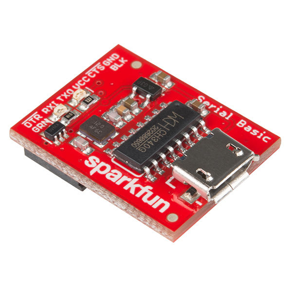
Do do this, use 3.3V (and NOT 5V) FTDI USB/Serial adapter, I love this one from sparkun
- Connect FTDI on the 6 pins dedicated header of the breakout
- use them a terminal application and open the port on your computer corresponding to the FTDI device
- set terminal settings to 9600 bauds 8 bits no parity 1 stop bit (8N1)
- check with at command
ATdevice should anwser+AT: OK
then get keys of the device
AT
+AT: OK
AT+ID
+ID: DevAddr, 24:90:05:44
+ID: DevEui, 2C:F7:F1:20:24:90:05:44
+ID: AppEui, 80:00:00:00:00:00:00:06
Provision device on Network Server
For testing I'm always using The Things Network (TTN). So next step is to provision this new device to TTN with the above keys (no need DevAddr) and get APPKEY from TTN (random generate) then get the key issued from TTN (we'll use it later below)
Compile and flash Firmware
You can flash the board with excellent mbed-os framework. Easy way is to use mbed studio IDE. We added this board into stm32customtargets, don't hesitate to read the readme. Finally the main firmware mbed-os-example-lorawan program.
Once IDE installed:
- use
file/import programand them import the example with URLhttps://github.com/ARMmbed/mbed-os-example-lorawan - right click in the project name and select
Add Libraryand enterhttps://github.com/ARMmbed/stm32customtargets - open the file
custom_targets.jsonfrom folderstm32customtargetsand copy whole contents - paste copied contents in the main root folder file
custom_targets.json(yes replace the whole file) - open the file
mbed_app.jsonand change parameters on the sectiontarget_overrides- LoRaWAN parameters such as frequency plan, OTAA, Duty Cycle, ...
- replace keys with the ones you got from above step
lora.device-eui,lora.application-euiandlora.application-key
- add the following section near the end of the file
mbed_app.json.
        "LORA_E5_BREAKOUT": {
            "stm32wl-lora-driver.rf_switch_config": "RBI_CONF_RFO_HP",
            "stm32wl-lora-driver.debug_tx": "PB_5",
            "stm32wl-lora-driver.debug_rx": "PB_10",
            "stm32wl-lora-driver.debug_invert": 1,
            "stm32wl-lora-driver.rf_switch_config": 2,
        }
When using any LoRa-E5 board you need to set the line rf_switch_config as above to RBI_CONF_RFO_HP, because hardware has not wired the mode RBI_CONF_RFO_LP and the stack for EU868 will try to use the RBI_CONF_RFO_LP (Low Power because 14dB max) path, and thus will result in unreliable signal (see #3). See this post and this one for details.
Then on IDE select target "LORA_E5_BREAKOUT", build and flash with your favorite programmer (I'm using STLink) with GND/SWDIO/SWDCLK/RESET connected.
Pay attention, that 1st time you need to erase SeeeStudio original firmware, make sure the Read Out Protection of the device is AA. If it is shown as BB, select AA and click Apply. See the end of this section on how to do that with STM32CubeProgrammer.
Build and Flash
From IDE you can build the example. If you plug your STLink while project opened, mbed ide will ask you if you want to set it up for this project/target, once approved you can compile, flash and even debug from mbed ide (need some tools installed, read, very nice.

You can also see logs with the FTDI adapter and any Serial terminal set to 115200 bauds 8 bits no parity 1 stop bit (8N1)
Mbed LoRaWANStack initialized
 CONFIRMED message retries : 3
 Adaptive data  rate (ADR) - Enabled
 Connection - In Progress ...
 Connection - Successful
 Dummy Sensor Value = 3
 23 bytes scheduled for transmission
 Message Sent to Network Server
 Dummy Sensor Value = 5
 23 bytes scheduled for transmission
 Message Sent to Network Server
 Dummy Sensor Value = 7
 23 bytes scheduled for transmission
Green LED will be on when on receive mode and Red when sending data.
License
Same as original here https://wiki.seeedstudio.com/LoRa_E5_mini/ if any
