LiveOV7670 Save
A step-by-step guide to building the circuit for this project:
LiveOV7670
Demo:
https://www.youtube.com/watch?v=TqSY6FETuos&list=PLVilroPGLJaesaS5mP93i0goPck2JK-O4&index=2
Step-by-step guide with pictures:
https://circuitjournal.com/arduino-ov7670-10fps
Tutorial 1 (10fps video stream to a display):
https://www.youtube.com/watch?v=Dp3RMb0e1eA&index=3&list=PLVilroPGLJaesaS5mP93i0goPck2JK-O4
Tutorial 2 (sending image to the PC over the USB cable):
https://www.youtube.com/watch?v=L9DTW1ulsT0&index=5&list=PLVilroPGLJaesaS5mP93i0goPck2JK-O4
Datasheet for OV7670:
https://www.voti.nl/docs/OV7670.pdf
Compiling in Arduino IDE:
- Download all files
- copy "src/lib/LiveOV7670Library" and "src/lib/Adafruit_GFX_Library" to Arduino "libraries" folder (If you already have "Adafruit_GFX_Library" then you don't have to copy that)
- Open "src/LiveOV7670/LiveOV7670.ino" in Arduino IDE
- Select Tools->Board->Arduino Uno/Nano
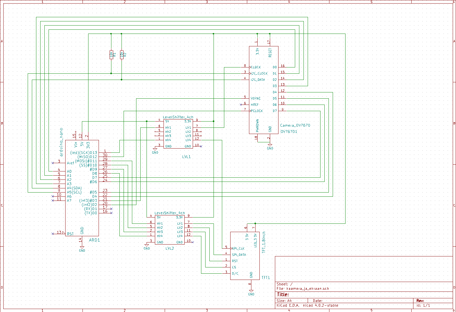
Connection shcema for the PCB board:
https://raw.githubusercontent.com/indrekluuk/LiveOV7670/master/LiveOV7670.png
Connections for Arduino Uno/Nano
OV7670 connections:
VSYNC - PIN2
XCLCK - PIN3 (must be level shifted from 5V -> 3.3V)
PCLCK - PIN12
SIOD - A4 (I2C data) - 10K resistor to 3.3V
SIOC - A5 (I2C clock) - 10K resistor to 3.3V
D0..D3 - A0..A3 (pixel data bits 0..3)
D4..D7 - PIN4..PIN7 (pixel data bits 4..7)
3.3V - 3.3V
RESET - 3.3V
GND - GND
PWDN - GND
1.8" TFT connections:
DC - PIN8 (5V -> 3.3V)
CS - PIN9 (5V -> 3.3V)
RESET - PIN10 (5V -> 3.3V)
SPI data - PIN11 (5V -> 3.3V)
SPI clock - PIN13 (5V -> 3.3V)
VCC - 5V/3.3V (depending on jumper position on the TFT board)
BL - 3.3V
GND - GND
Connections for Arduino Mega
OV7670 connections:
VSYNC - PIN2
XCLCK - PIN9 (must be level shifted from 5V -> 3.3V)
PCLCK - PIN12
SIOD - PIN20-SDA (I2C data) - 10K resistor to 3.3V
SIOC - PIN21-SCL (I2C clock) - 10K resistor to 3.3V
D0..D7 - PIN22..PIN29 (pixel data bits 0..7)
3.3V - 3.3V
RESET - 3.3V
GND - GND
PWDN - GND
1.8" TFT connections:
DC - PIN48 (5V -> 3.3V)
CS - PIN53 (5V -> 3.3V)
RESET - PIN49 (5V -> 3.3V)
SPI data - PIN51 (5V -> 3.3V)
SPI clock - PIN52 (5V -> 3.3V)
VCC - 5V/3.3V (depending on jumper position on the TFT board)
BL - 3.3V
GND - GND
Special thanks to https://github.com/ComputerNerd/ov7670-no-ram-arduino-uno
