Iz2k Flip Clock Save
Flip-Clock smart alarm-clock
Flip-Clock
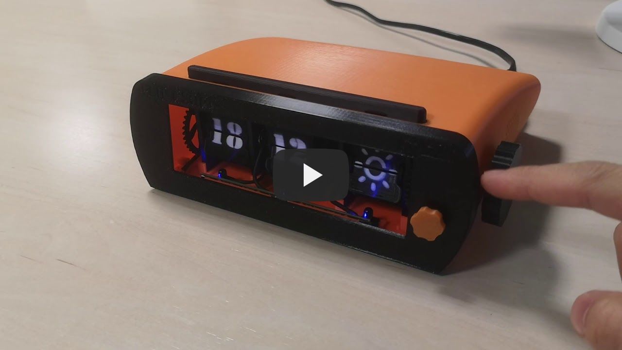
The Flip-Clock is an old stylish, classic alarm clock with up to date features, such as automatic time adjustment, weather forecast, FM radio or Spotify playback. The device consists of three 3D printed flip digits, a PCB with integrated drivers for the digit controlling stepper motors and a Raspberry Pi 3 A+ with 3W speakers to run the main code.
All the mechanics and electronics are mounted within an 3D printed elegant cover. Additionally, a snoozer bar, two rotary encoders and a RGBW LED strip are included for the user interface.
 |
 |
|---|---|
 |
 |
Find additional info about each design in:
Parts
3D printed flip digits
Each flip digit consists of a support structure with two bearings. The axle is placed inside the bearings holding two flap holders. All the flaps are mounted within those holders. The movement of the digit is achieved with a stepper motor and two gears. An IR transmitter and an IR receiver are palced on the top and on the bottom of the flaps to detect transitions. Additionally, a limit switch is placed close to the gears to synchronize with it each turn.
Subparts
- Support structure
- Bearings (623-2RS)
- Axle
- Flap holders
- Flaps
- Gears
- Stepper motor (28BYJ-48)
- IR transmitter (IR diode)
- IR receiver (IR photodiode)
- Limit switch (CLW1093)

FlipDigitController PCB
The FlipDigitController PCB includes a microcontroller and drivers to control the stepper motors. Additionally, the PCB also handles the IR transmitter and receiver to detect flap transitions and the limit switch for automatic synchronization of the axle. The PCB has an UART interface for the abstraction layer protocol.
The current version of the PCB can handle up to two flip digits at the same time. For the FlipClock device two units of the PCB have been used: one to control hours and minutes flaps, and another one to control weather flaps.
| Block diagram | Layout |
|---|---|
 |
 |
Subparts
3D printed cover

Subparts
- 3D printed top cover
- 3D printed bottom cover
- 3D printed front cover
- 3D printed back cover
Rotary encoders
For the user interface two rotary encoders have been used. The used encoders can detect steps in both directions, and include a built-in switch. One of the encoders is used to control the volume (up/down/mute), whereas the other encoder controls the audio device (FM Radio/Spotify/OFF)
| Wheels | Encoders |
|---|---|
 |
 |
Subparts
- 3D printed volume wheel
- 3D printed control wheel
- TT EN11-HSM1AF15 Rotary Encoders
Snooze bar
A snooze bar is included on top of the FlipClock device. This bar can be used to trigger the nightlight by default, or to stop/snooze the alarm when it has been triggered. Tactile switches are placed under the bar to detect when it is pressed.
| Bar | Switch |
|---|---|
 |
 |
Subparts
- 3D printed snooze bar
- EVQ-Q2S03W tactile switches
NeoPixel RGBW Stick
Two NeoPixel RGBW LED sticks have been included in the front of the FlipClock in order to provide nightlight and light-sign functions to the device.

Subparts
3W Speakers

Subparts
FM radio tunner (RTL-SDR)
| RTL-SDR dongle | FM antenna |
|---|---|
 |
 |
Subparts
Raspberry Pi 3 A+
| Raspberry Pi 3 Model A+ | Adafruit I2S 3W Stereo Speaker Bonnet |
|---|---|
 |
 |
Subparts
Power Supply
| Power Supply Module | PSM Housing |
|---|---|
 |
 |
Subparts
- PS-05-5 power supply module
- 3D printed housing
Wiring
The correct wiring to connect the different electronics is as follows:
PSM connection:
| Subpart | PIN | PIN | Subpart |
|---|---|---|---|
| RPI3 | 5V | 5V | PSM |
| RPI3 | GND | GND | PSM |
NeoPixel connection:
| Subpart | PIN | PIN | Subpart |
|---|---|---|---|
| NeoPixel | DIN | MOSI | RPI3 |
| NeoPixel | 5VDC | 5V | RPI3 |
| NeoPixel | GND | GND | RPI3 |
Snooze Bar connection:
| Subpart | PIN | PIN | Subpart |
|---|---|---|---|
| Snooze Bar | SW0 | GPIO 4 | RPI3 |
| Snooze Bar | SW1 | GPIO 17 | RPI3 |
Volume Encoder1 connection:
| Subpart | PIN | PIN | Subpart |
|---|---|---|---|
| Volume Encoder | SW0 | GPIO 24 | RPI3 |
| Volume Encoder | SW1 | GPIO 25 | RPI3 |
| Volume Encoder | ROT0 | GPIO 27 | RPI3 |
| Volume Encoder | ROT1 | GPIO 23 | RPI3 |
| Volume Encoder | GND | GPIO 22 | RPI3 |
Control Encoder1 connection:
| Subpart | PIN | PIN | Subpart |
|---|---|---|---|
| Control Encoder | SW0 | GPIO 5 | RPI3 |
| Control Encoder | SW1 | GPIO 6 | RPI3 |
| Control Encoder | ROT0 | GPIO 12 | RPI3 |
| Control Encoder | ROT1 | GPIO 16 | RPI3 |
| Control Encoder | GND | GPIO 13 | RPI3 |
Flip-Clock-Controller PCB:
| Subpart | PIN | PIN | Subpart |
|---|---|---|---|
| RPI3 | 3.3V | 3.3V | Flip-Clock-Controller PCB 1 (HHMM) |
| RPI3 | 3.3V | 3.3V | Flip-Clock-Controller PCB 2 (WW) |
| RPI3 | TX | RX | Flip-Clock-Controller PCB 1 (HHMM) |
| Flip-Clock-Controller PCB 1 (HHMM) | TX | RX | Flip-Clock-Controller PCB 2 (WW) |
| Flip-Clock-Controller PCB 2 (WW) | TX | RX | RPI3 |
1: For ease of connectivity, all pins of rotary encoders are routed to GPIOs. These GPIOs will be configured as required with pull resistors or fixed voltages via software.
