Ingress Table Save
Ingress Table NoFlo & MicroFlo setup
Ingress Table 

The software side of a "physical Intel map", built with NoFlo and MicroFlo. Please read the introductory blog post for more information. The actual table can be seen live at the c-base space station in Berlin.

How does this work?
We have a NoFlo graph that periodically pulls portal status information from the data provider, and converts that to status information to be shown on the table surface.
The status information is then transmitted to a microcontroller that shows portal owners, attack notifications, etc. using the LEDs.
At c-base the table runs as part of the c-flo IoT network, with the data fetching part running on a server machine, and the light control running inside the table itself. Messaging related to these is coordinated by MsgFlo.
Starting and Stopping the Service
Clone this repository to /opt/ingress-table on your system, add an authorized access token as cookie.json, npm install dependencies.
Copy the systemd service files from systemd/ folder to /etc/systemd/system
Reload systemd files with sudo systemctl daemon-reload
Start the services with:
-
sudo systemctl start ingress-data(for the API interface part) -
sudo systemctl start ingress-lights(for the light control)
Hardware
- Raspberry Pi running NoFlo
- Arduino Uno running Microflo for controlling the WS2801-based LED strand (portal lights)
- 50 individually controllable LEDs for portals (based on the WS2801 controller chip)
- 5 LED strips for streets (map background) and floor lighting
- Launchpad Tiva running MicroFlo for controlling the 5 RGB-LED strips
- USB chargers for agents running out of battery
LED driver circuit
The RGB-LED strips we use run on 12 Volts DC and have one shared plus pole and an individual minus pole for each color. They cannot be driven by the Tiva itself so we use an N-Channel MOSFET to control them. We use three IRL540N MOSFETs (named Q1, Q2, Q3) per RGB strip.
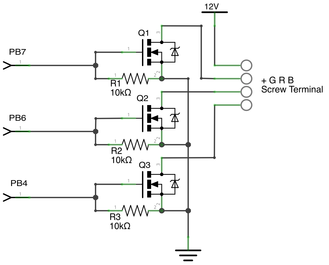
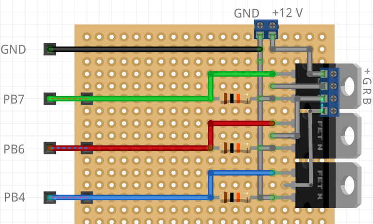
This is the circuit for one channel only, you must build this 5 times. Here is an example of how you could put in on a perfboard:
LED strip i/o pins
J2
---

PB7 Green1
PB6 Blue1

PA2 -> SSI0Clk => Portallights Clock (CKI), not used at the moment

J4
---

PF3 Red2
PC4 Green2
PC5 Blue2

PF2 Red Bottom

J3
---

PD0 Red3
PD1 Green3
PF1 Blue3

J1
---
PB4 Red1
PB5 Red4
PE4 Green4
PE5 Blue4

PA6 Green Bottom
PA7 Blue Bottom

PA5 -> SSI0Tx => Portallights Data (SDI), not used at the moment
Note: out-of-the box on the Tiva the pins PB6, PB7, PD0, PD1 can't be used. You can disconnect the R9 and R10 resistors to make them usable.
Flashing and resetting the Arduino
Resetting the MCU:
stty -F /dev/ttyACM1 1200

make upload SERIALPORT=/dev/ttyACM1 BAUDRATE=57600 MODEL=leonardo GRAPH=../ingress-table/graphs/PortalLights.fbp
