ATtiny85 USB Tester Save
Simple USB Power Tester
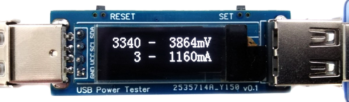
USB Power Tester
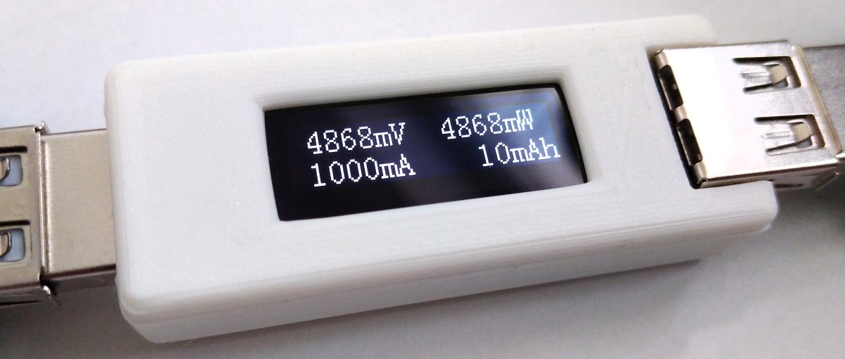
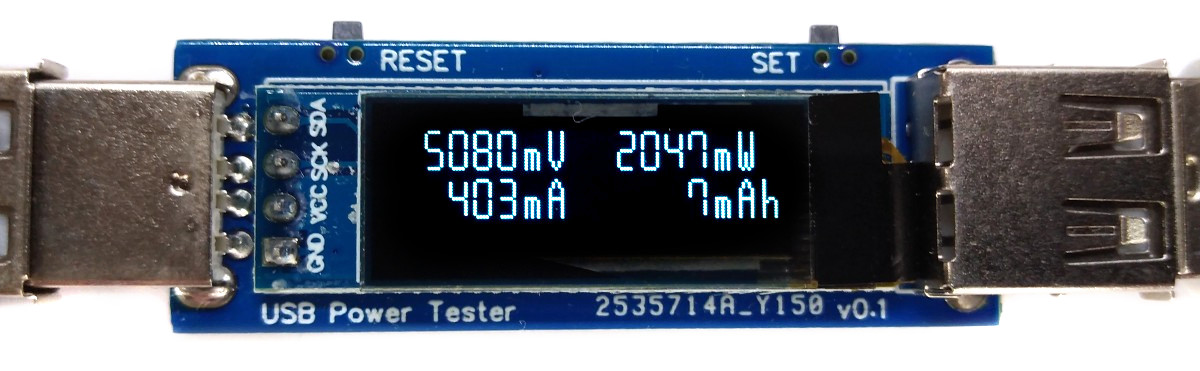
Simple USB Power Tester based on ATtiny25/45/85 and INA219. The device measures voltage, current, power, energy, capacity and displays the values on an OLED screen. You can switch between different screens by pressing the SET button.
- Project Video (YouTube): https://youtu.be/QKx8Vn_IfjU
- Design Files (EasyEDA): https://easyeda.com/wagiminator/attiny85-usb-tester
Hardware
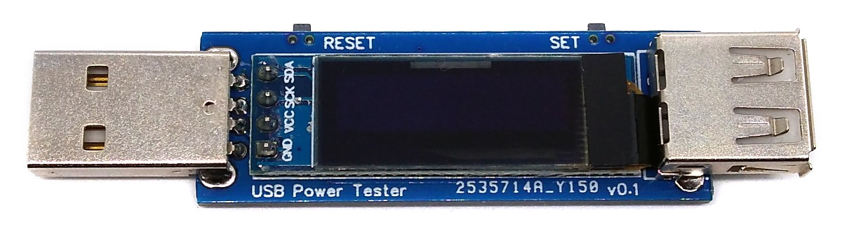
USB Connectors
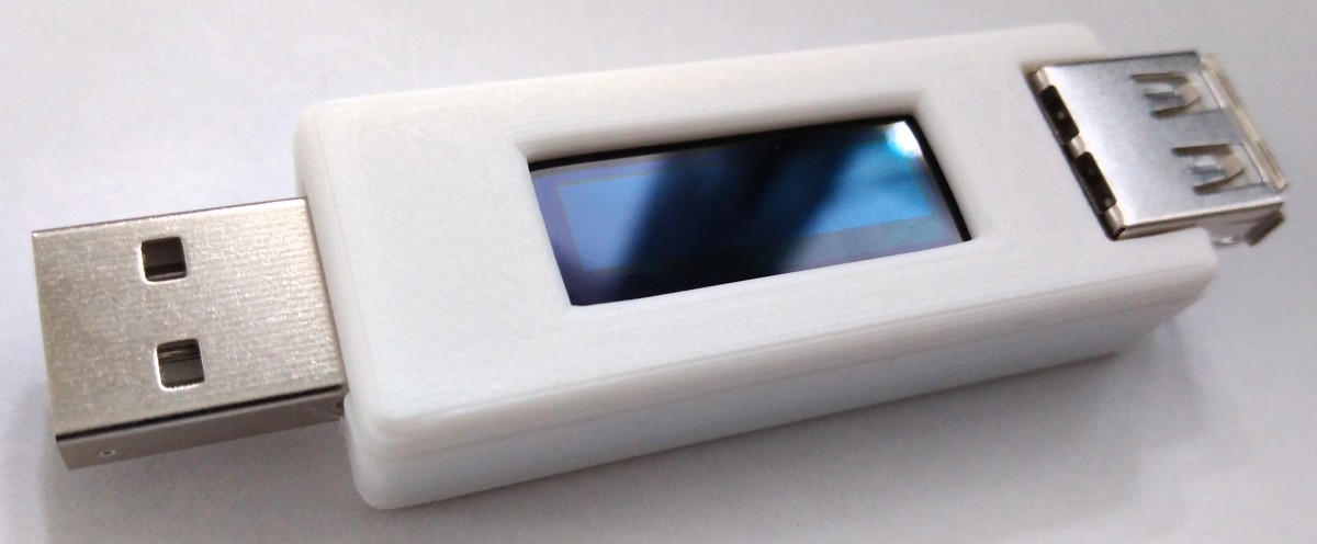
The device is equipped with a USB-A plug for the input and a USB-A socket for the output, so that it can be plugged between the power supply and the consumer. D+ and D- are passed through so that the consumer can negotiate the charging protocol.
Voltage and Current Measurement
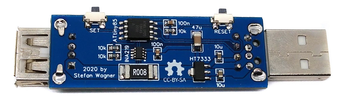
An INA219 is used to measure voltage and current. The INA219 is a current shunt and power monitor with an I²C-compatible interface. The device monitors both shunt voltage drop and bus supply voltage, with programmable conversion times and filtering. A programmable calibration value, combined with an internal multiplier, enables direct readouts of current in amperes. The selected shunt resistance of 8mΩ enables both a very small influence on the circuit and a measurement with a resolution of 1mA. For an accurate measurement, a shunt resistor with a low tolerance (1% or better) should be selected.
User Interface
The user interface utilizes two buttons and an SSD1306 128x32 pixels OLED display. An ATtiny24/45/85 microcontroller handles the user interface as well as the calculation and display of the values.
Software
Basic Principle
The INA219 continuously measures current and voltage and transmits the values to the ATtiny via I²C. From this, the ATtiny calculates the other values and displays them on the OLED screen.
I²C OLED Implementation
The I²C protocol implementation is based on a crude bitbanging method. It was specifically designed for the limited resources of ATtiny10 and ATtiny13, but it works with some other AVRs (including the ATtiny25/45/85) as well. The functions for the OLED are adapted to the SSD1306 OLED module, but they can easily be modified to be used for other modules. In order to save resources, only the basic functionalities which are needed for this application are implemented. For a detailed information on the working principle of the I²C OLED implementation visit TinyOLEDdemo.
Accuracy of Time and Capacity Determination
The internal oscillator of the ATtiny is used to determine energy and capacity. The accuracy of the internal oscillator is +/-10% with the factory calibration. This can be improved to +/-2% or better by manual calibration. The calibration value determined in this way can be set in the source code.
Compiling and Uploading
Since there is no ICSP header on the board, you have to program the ATtiny either before soldering using an SOP adapter, or after soldering using an EEPROM clip. The AVR Programmer Adapter can help with this.
If using the Arduino IDE
- Make sure you have installed ATtinyCore.
- Go to Tools -> Board -> ATtinyCore and select ATtiny25/45/85 (No bootloader).
- Go to Tools and choose the following board options:
- Chip: ATtiny25 or 45 or 85 (depending on your chip)
- Clock: 1 MHz (internal)
- B.O.D.Level: B.O.D. enabled (2.7V)
- Leave the rest at the default settings
- Connect your programmer to your PC and to the ATtiny.
- Go to Tools -> Programmer and select your ISP programmer (e.g. USBasp).
- Go to Tools -> Burn Bootloader to burn the fuses.
- Open USB_Tester sketch and click Upload.
If using the precompiled hex-file
- Make sure you have installed avrdude.
- Connect your programmer to your PC and to the ATtiny.
- Open a terminal.
- Navigate to the folder with the hex-file.
- Execute the following command (if necessary replace "usbasp" with the programmer you use):
avrdude -c usbasp -p t85 -U lfuse:w:0x62:m -U hfuse:w:0xd5:m -U efuse:w:0xff:m -U flash:w:usb_tester.hex
If using the makefile (Linux/Mac)
- Make sure you have installed avr-gcc toolchain and avrdude.
- Connect your programmer to your PC and to the ATtiny.
- Open a terminal.
- Navigate to the folder with the makefile and the Arduino sketch.
- Run
DEVICE=attiny85 PROGRMR=usbasp make installto compile, burn the fuses and upload the firmware (change DEVICE and PROGRMR accordingly).
Operating Instructions
- Connect the device between a power supply and a consumer.
- Use the SET button to switch between the different screens.
- Use the RESET button to reset all values.
Characteristics
| Parameter | Value |
|---|---|
| Voltage | 3V - 12V |
| Current | max 5A |
| Voltage Measurement Resolution | 4mV |
| Current Measurement Resolution | 1mA |
References, Links and Notes
- UBS Type-C Version
- ATtiny25/45/85 Datasheet
- INA219 Datasheet
- SSD1306 Datasheet
- 128x32 OLED on Aliexpress
License

This work is licensed under Creative Commons Attribution-ShareAlike 3.0 Unported License. (http://creativecommons.org/licenses/by-sa/3.0/)
