ATtiny85 TinyLoad Save
Electronic Dummy Load
TinyLoad - Simple Electronic Load based on ATtiny45/85
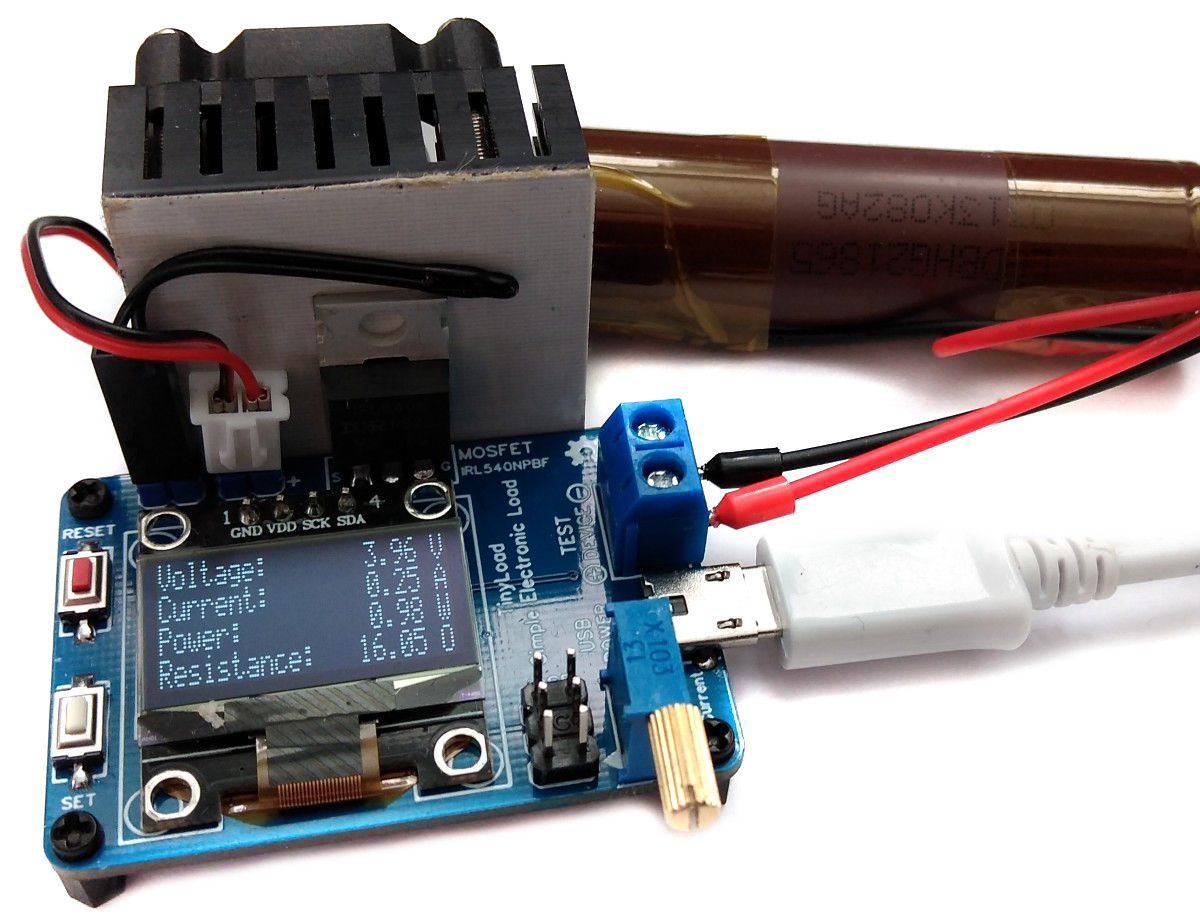
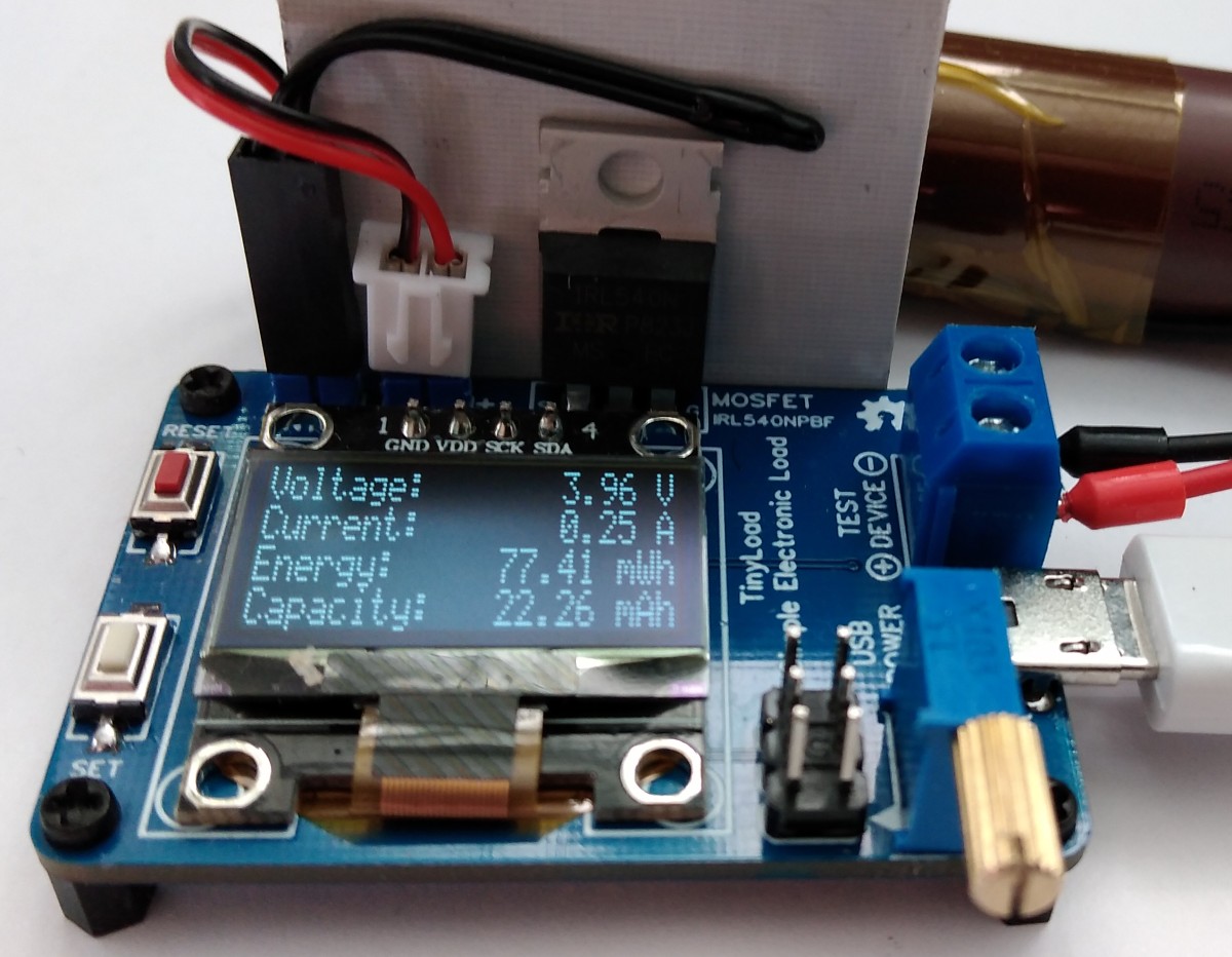
TinyLoad is a simple electronic constant current dummy load. The ATtiny measures voltage, current and temperature of the heat sink, calculates power, energy and battery capacity, controls the fan and displays all relevant data on the OLED. The button is used to switch between power/resistance and energy/capacity display.
- Project Video (YouTube): https://youtu.be/z7fddsFyD1E
- Design Files (EasyEDA): https://easyeda.com/wagiminator/y-attiny85-electronic-load
Hardware
The electronic load control circuit, which essentially consists of a potentiometer, an operational amplifier, a MOSFET and a shunt resistor, ensures that the same current flows regardless of the voltage applied.
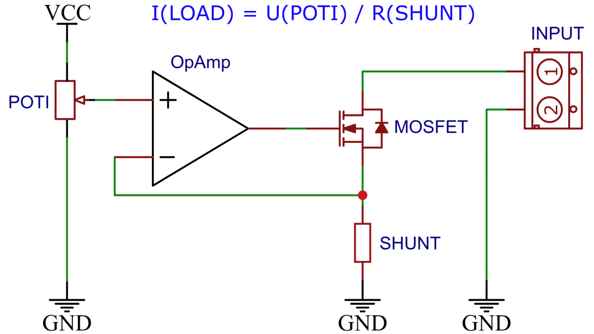
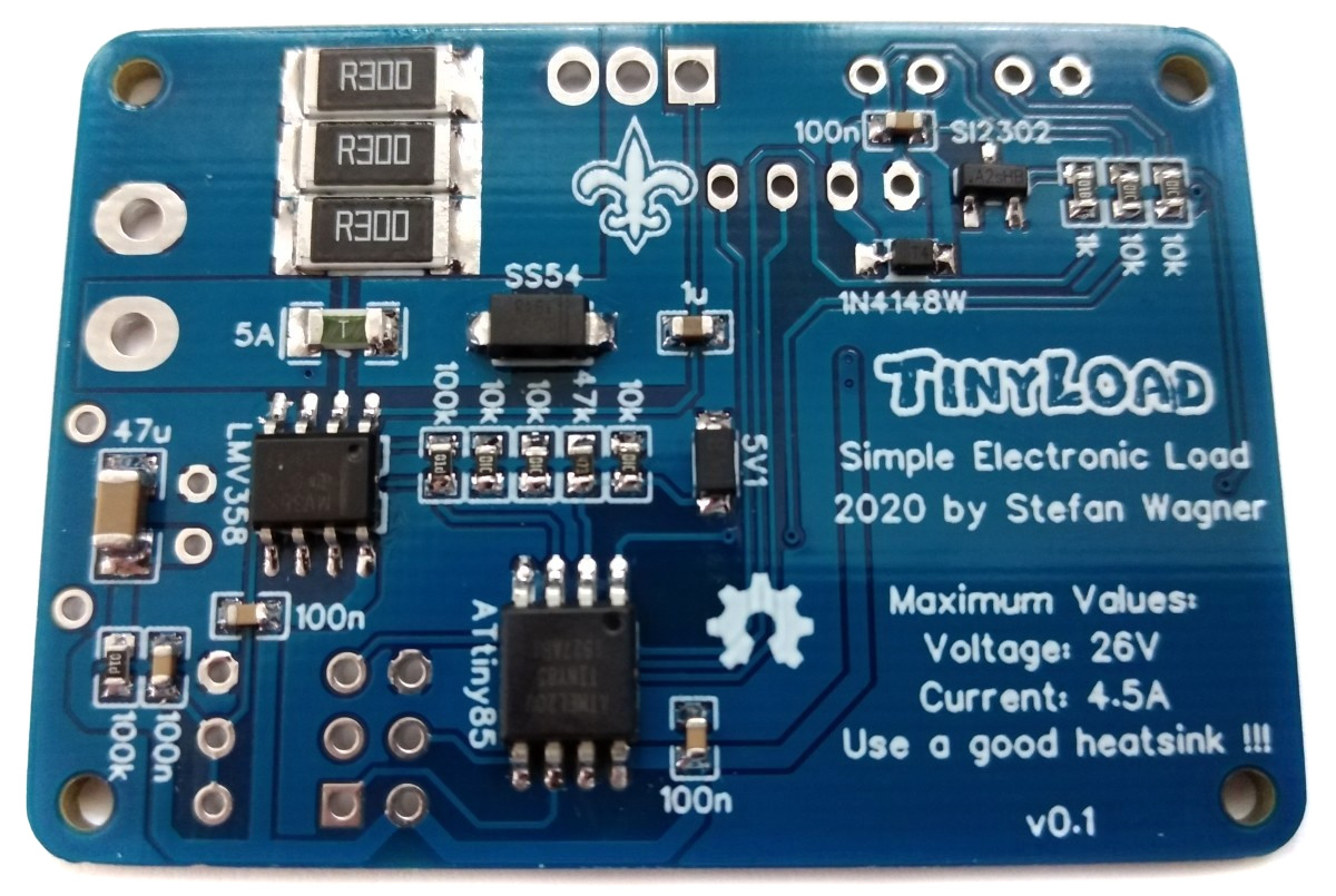
For this purpose, a 100 milliohms shunt consisting of three 300 milliohms resistors in parallel for proper heat dissipation is located in the load circuit, via which the current is measured. The LMV358 rail-to-rail OpAmp compares this with the target value, which is specified via a 10-turn 10k potentiometer and a 100k resistor and accordingly controls the gate of an IRL540N logic level power MOSFET, which in turn adjusts the current through its internal resistance set in this way. The current measured at the shunt is also amplified by a second OpAmp and measured by the ADC of the ATtiny. The voltage is measured using a voltage divider. The temperature of the MOSFET is measured by a 10k 3950B NTC thermistor. If necessary, the fan is switched on via a MOSFET.
Software
Measurements
For the most accurate measurement possible with maximum measurement resolution, both the 5V supply voltage and the two internal reference voltages in connection with the ADC of the ATtiny are used. First, the supply voltage and the 2.56V reference are measured using the 1.1V reference and corresponding calibration factors are calculated. For each pending measurement, it is first checked which of the three voltage references (5V, 2.56V or 1.1V) is most suitable. This is then used for the measurement via the ADC. For all ADC measurements, the ATtiny is set to sleep mode in order to avoid noise that is generated by the MCU (ADC noise canceler). To further increase the measurement resolution, 64 measurements are carried out in succession (oversampling) and the measured values are added up. The averaging is only carried out at the end of the further calculations in order not to lose any measurement resolution. The measurement accuracy depends essentially on the accuracy of the internal 1.1V reference. This can be calibrated manually if necessary.
Accuracy of Energy and Capacity Determination
The internal oscillator of the ATtiny is used to determine energy and electric charge (capacity). The accuracy of the internal oscillator is +/-10% with the factory calibration. This can be improved to +/-2% or better by manual calibration.
I²C OLED Implementation
The I²C protocol implementation is based on a crude bitbanging method. It was specifically designed for the limited resources of ATtiny10 and ATtiny13, but it works with some other AVRs (including the ATtiny25/45/85) as well. The functions for the OLED are adapted to the SSD1306 OLED module, but they can easily be modified to be used for other modules. In order to save resources, only the basic functionalities which are needed for this application are implemented. For a detailed information on the working principle of the I²C OLED implementation visit TinyOLEDdemo.
Compiling and Uploading
If using the Arduino IDE
- Make sure you have installed ATtinyCore.
- Go to Tools -> Board -> ATtinyCore and select ATtiny25/45/85 (No bootloader).
- Go to Tools and choose the following board options:
- Chip: ATtiny45 or 85 (depending on your chip)
- Clock: 1 MHz (internal)
- B.O.D.Level: B.O.D. enabled (2.7V)
- Leave the rest at the default settings
- Connect your programmer to your PC and to the ICSP header on the board.
- Go to Tools -> Programmer and select your ISP programmer (e.g. USBasp).
- Go to Tools -> Burn Bootloader to burn the fuses.
- Open TinyLoad sketch and click Upload.
If using the precompiled hex-file
- Make sure you have installed avrdude.
- Connect your programmer to your PC and to the ATtiny.
- Open a terminal.
- Navigate to the folder with the hex-file.
- Execute the following command (if necessary replace "t85" with your chip and "usbasp" with the programmer you use):
avrdude -c usbasp -p t85 -U lfuse:w:0x62:m -U hfuse:w:0xd5:m -U efuse:w:0xff:m -U flash:w:tinyload.hex
If using the makefile (Linux/Mac)
- Make sure you have installed avr-gcc toolchain and avrdude.
- Connect your programmer to your PC and to the ICSP header of the device.
- Open a terminal.
- Navigate to the folder with the makefile and the Arduino sketch.
- Run
DEVICE=attiny85 PROGRMR=usbasp make installto compile, burn the fuses and upload the firmware (change DEVICE and PROGRMR accordingly).
Operating Instructions
Usage
- Turn the potentiometer full counter-clockwise.
- Connect the device via the Micro-USB connector to a 5V power supply.
- Connect the test power supply to the block terminal. Pay attention to the correct polarity!
- Turn the potentiometer clockwise to choose the desired load current.
Calibration
The ADC and the internal reference voltages of the ATtiny do their best to make the tinyLoad a pretty accurate tool, but it might need a little calibration. How to calibrate:
- Set ULCAL and ILCAL to "1" in the sketch, compile and upload.
- Choose a stable input voltage of around 5V and turn the poti until the display shows a current of around 0.7A. Measure the voltage and the current with a trusty multimeter or a good lab bench power supply.
- Calculate the calibration factors as follows:
- ULCAL = voltage measured with multimeter / voltage shown on OLED.
- ILCAL = current measured with multimeter / current shown on OLED.
- Set the ULCAL and ILCAL value in the sketch, compile and upload again.
Precautions
- Use a good heatsink with a 5V fan for the MOSFET !
- Be careful with high power loads ! This device is called "tinyLoad" for a reason !
- Always turn the POTI full counter-clockwise before connecting the load !
- Due to the input offset voltage of the OpAmp the minimum load current is 17mA. You can use a better OpAmp like the OPA2330 or OPA2333 if you like.
- The maximum load current is 4.5A, however for small voltages it might be less.
- Do not exceed the maximum voltage of 26V !
References, Links and Notes
License

This work is licensed under Creative Commons Attribution-ShareAlike 3.0 Unported License. (http://creativecommons.org/licenses/by-sa/3.0/)
