ATtiny13 TinyRemoteXL Save
12-Button IR Remote Control
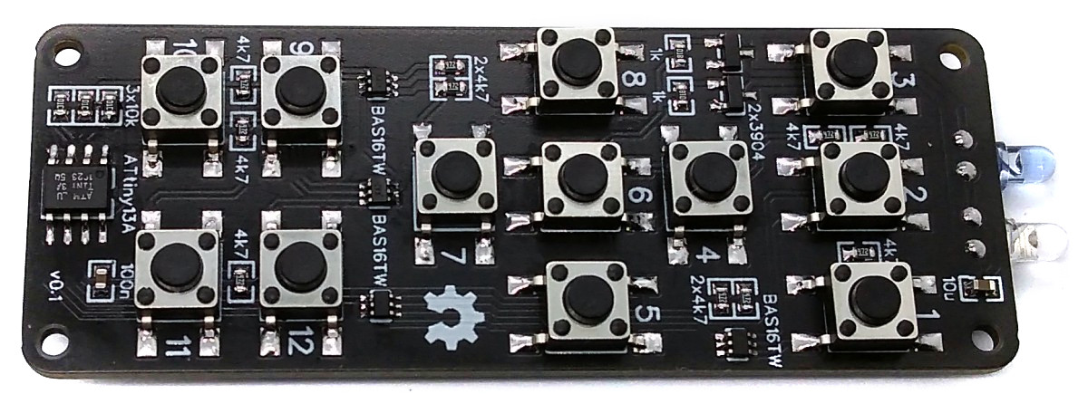
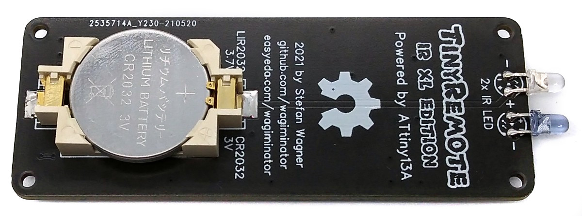
TinyRemoteXL - 12-Button IR Remote Control based on ATtiny13A
TinyRemoteXL is a 12-button IR remote control based on an ATtiny13A powered by a CR2032 or LIR2032 coin cell battery.
- Design Files (EasyEDA): https://easyeda.com/wagiminator/attiny13-tinyremoteir-xl
Hardware
The basic hardware is similar to the 5-button TinyRemote. The main difference is that the ATtiny13 has to query 12 buttons here. There are various options for using a larger number of buttons with just a few pins. However, most of them do not meet the following conditions:
- there are only four pins available for twelve buttons,
- a keystroke must trigger an asynchronous interrupt to wake the ATtiny from deep sleep mode,
- the circuit must not consume any electricity as long as no button is pressed.
A combination of voltage dividers and a couple of diodes does the trick:
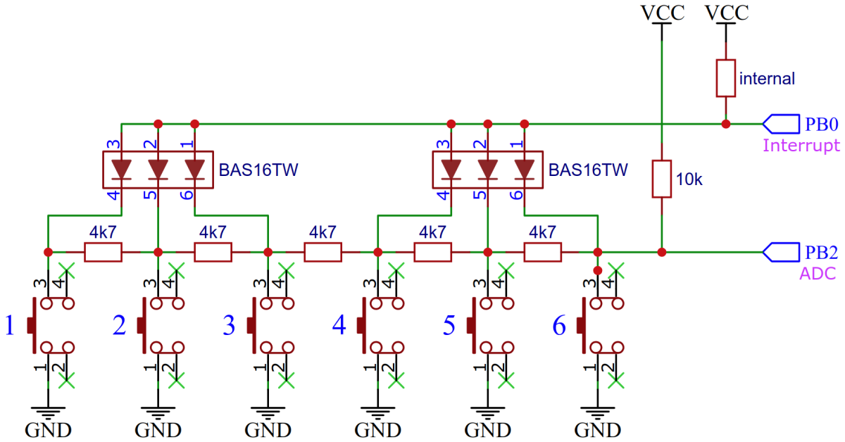
If, for example, button 4 is pressed, pin PB0 is pulled to ground via the corresponding diode and a pin change interrupt is triggered, which wakes up the ATtiny. The diodes prevent the 4k7 resistors of the voltage divider from shorting out. The voltage that can be measured at PB2 via the ADC results from the supply voltage divided by the 10k resistor on the upper side and two 4k7 resistors (= 9k4) on the lower side. This value depends on the key pressed.
Software
IR Protocol Implementation
The implementation for the NEC, SAMSUNG, SONY and RC-5 protocol is taken from TinyRemote. Refer to this project for a complete explanation.
Setting the IR Codes
Before compiling you have to define the IR commands for each button. Different protocols and device addresses can be used. Several codes can also be assigned to a single key, separated by semicolons.
#define KEY1  NEC_sendCode(0x04,0x08)     // LG TV Power: addr 0x04, cmd 0x08
#define KEY2  RC5_sendCode(0x00,0x0B)     // Philips TV Power: addr 0x00, cmd 0x0B
#define KEY3  SON_sendCode(0x01,0x15,12)  // Sony TV Power: addr 0x01, cmd 0x15, 12-bit version
#define KEY4  SAM_sendCode(0x07,0x02)     // Samsung TV Power: addr: 07, cmd: 02
#define KEY5  NEC_sendCode(0xAB04,0x08);SON_sendCode(0xE401,0x15,20)
[...]
Button Detection
If a key has been pressed, a pin change interrupt is triggered and the ATtiny is brought out of sleep mode. The pressed key is then identified via the voltage divider between the individual keys using the ADC of the ATtiny.
// Pin assignments
#define BINT1_PIN   PB0       // interrupt pin for buttons 1..6
#define BINT2_PIN   PB3       // interrupt pin for buttons 7..12
#define BADC1_AP    1         // ADC port for buttons 1..6
#define BADC2_AP    2         // ADC port for buttons 7..12

// Button ADC thresholds
const uint8_t THRESHOLDS[] PROGMEM = {217, 173, 158, 136, 103, 41, 0};

// ADC read button row and return button number
uint8_t readButtonRow(uint8_t port) {
  PRR     = 0;                            // power on ADC
  ADMUX   = (1<<ADLAR) | port;            // set port, Vcc as reference, 8-bit sample
  ADCSRA |= (1<<ADEN) | (1<<ADSC);        // enable ADC and start sampling
  while (ADCSRA & (1<<ADSC));             // wait until sampling complete
  uint8_t raw = ADCH;                     // read sampling result (8 bits)
  ADCSRA &= ~(1<<ADEN);                   // disable ADC
  PRR     = 1<<PRADC;                     // shut down ADC
  uint8_t  button = 0;                    // figure out button number
  while (raw < pgm_read_byte(&THRESHOLDS[button])) button++;
  return button;                          // return button number
}

// Read and return button number (0 = no button)
uint8_t readButton(void) {
  uint8_t  button = 0;                    // start with number 0
  if (~PINB & (1<<BINT1_PIN)) button = readButtonRow(BADC1_AP);
  else if (~PINB & (1<<BINT2_PIN)) {
    button = readButtonRow(BADC2_AP);
    if (button) button += 6;
  }
  return button;                          // return button number
}

// Main function
int main(void) {
  [...]
  // Setup ADC to read button values
  ADCSRA = (1<<ADPS1)|(1<<ADPS0);       // set ADC prescaler 8
  [...]
  // Main loop
  while(1) {
    sleep_mode();                       // sleep until button is pressed
    _delay_ms(1);                       // debounce
    uint8_t button = readButton();      // read button number
    switch (button) {                   // send corresponding IR code
      case  1:  KEY1;  break;
      case  2:  KEY2;  break;
      [...]
      default: break;
    }
  }
}

// Pin change interrupt service routine
EMPTY_INTERRUPT (PCINT0_vect);          // nothing to be done here, just wake up from sleep
Power Saving
The code shuts down unused peripherals and utilizes the sleep mode power down function. It wakes up on every button press by pin change interrupt.
// Disable unused peripherals and prepare sleep mode to save power
ACSR  =  1<<ACD;                      // disable analog comperator
DIDR0 = ~BT_MASK & 0x1F;              // disable digital intput buffer except button INT
PRR   =  1<<PRADC;                    // shut down ADC
GIMSK =  1<<PCIE;                     // turn on pin change interrupts
PCMSK =  BT_MASK;                     // turn on interrupt on button pins
sei();                                // enable global interrupts
set_sleep_mode(SLEEP_MODE_PWR_DOWN);  // set sleep mode to power down
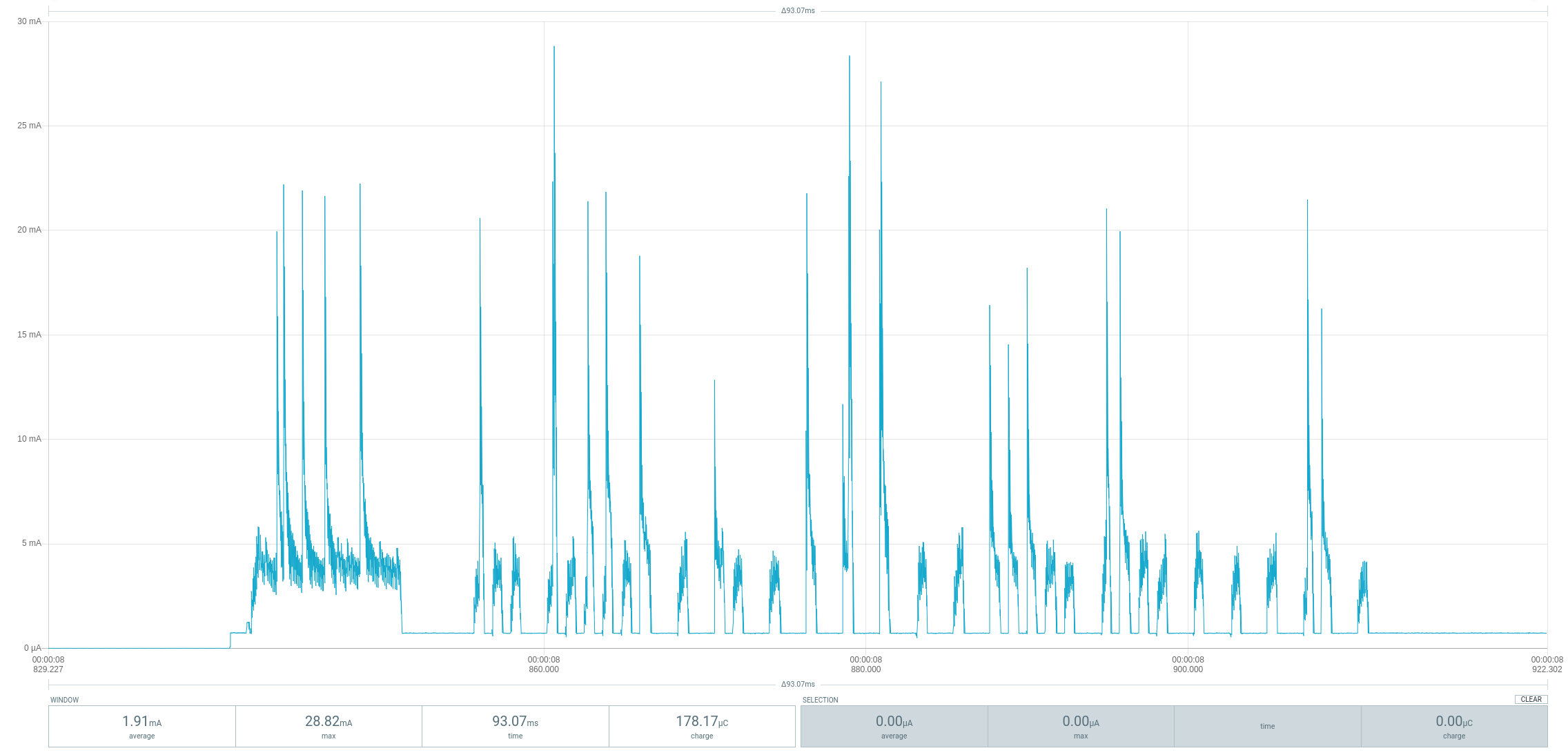
As long as no button is pressed, the ATtiny remains in sleep mode power down and consumes a current of around 100nA at a voltage of 3V. The typical capacity of a CR2032 battery is 230mAh. This results in a theoretical battery life of 2.3 million hours or 269 years. In real life, of course, no battery will last that long due to its self-discharge. When the button is pressed, peaks of up to 30mA are consumed. The diagram below shows the course of the current consumption when a button is pressed according to a measurement with the Power Profiler Kit II:
Timing Accuracy
The accuracy of the internal oscillator of the ATtiny13 is +/-10% with the factory calibration. Usually this is sufficient for an infrared remote control. Slight deviations in timing are tolerated by the receiver, since cheap remote controls are usually not more accurate. Nevertheless, it is recommended to manually calibrate the internal oscillator and set the corresponding OSCCAL value at the beginning of the code.
// oscillator calibration value (uncomment and set if necessary)
#define OSCCAL_VAL  0x48
Compiling and Uploading
Since there is no ICSP header on the board, you have to program the ATtiny either before soldering using an SOP adapter, or after soldering using an EEPROM clip. The AVR Programmer Adapter can help with this.
If using the Arduino IDE
- Make sure you have installed MicroCore.
- Go to Tools -> Board -> MicroCore and select ATtiny13.
- Go to Tools and choose the following board options:
- Clock: 1.2 MHz internal osc.
- BOD: BOD disabled
- Timing: Micros disabled
- Connect your programmer to your PC and to the ATtiny.
- Go to Tools -> Programmer and select your ISP programmer (e.g. USBasp).
- Go to Tools -> Burn Bootloader to burn the fuses.
- Open the TinyRemoteXL sketch and click Upload.
If using the precompiled hex-file
- Make sure you have installed avrdude.
- Connect your programmer to your PC and to the ATtiny.
- Open a terminal.
- Navigate to the folder with the hex-file.
- Execute the following command (if necessary replace "usbasp" with the programmer you use):
avrdude -c usbasp -p t13 -U lfuse:w:0x2a:m -U hfuse:w:0xff:m -U flash:w:tinyremotexl.hex
If using the makefile (Linux/Mac)
- Make sure you have installed avr-gcc toolchain and avrdude.
- Connect your programmer to your PC and to the ATtiny.
- Open a terminal.
- Navigate to the folder with the makefile and sketch.
- Run
PROGRMR=usbasp make installto compile, burn the fuses and upload the firmware (change PROGRMR accordingly).
References, Links and Notes
- TinyRemote
- TinyRemote RF
- IR remote control explanations by San Bergmans
- IR remote control by Christoph Niessen (german)
- IR remote control detective by David Johnson-Davies
- Infrared communication concepts (altium.com)
- NEC decoder based on ATtiny13A
- OSC Calibrator
- ATtiny13A datasheet
License

This work is licensed under Creative Commons Attribution-ShareAlike 3.0 Unported License. (http://creativecommons.org/licenses/by-sa/3.0/)
