ATtiny13 TinyRemote Save
IR Remote Control
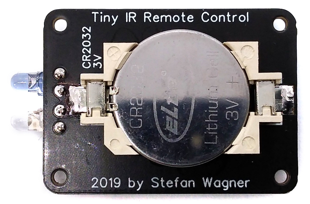
TinyRemote - IR Remote Control based on ATtiny13A
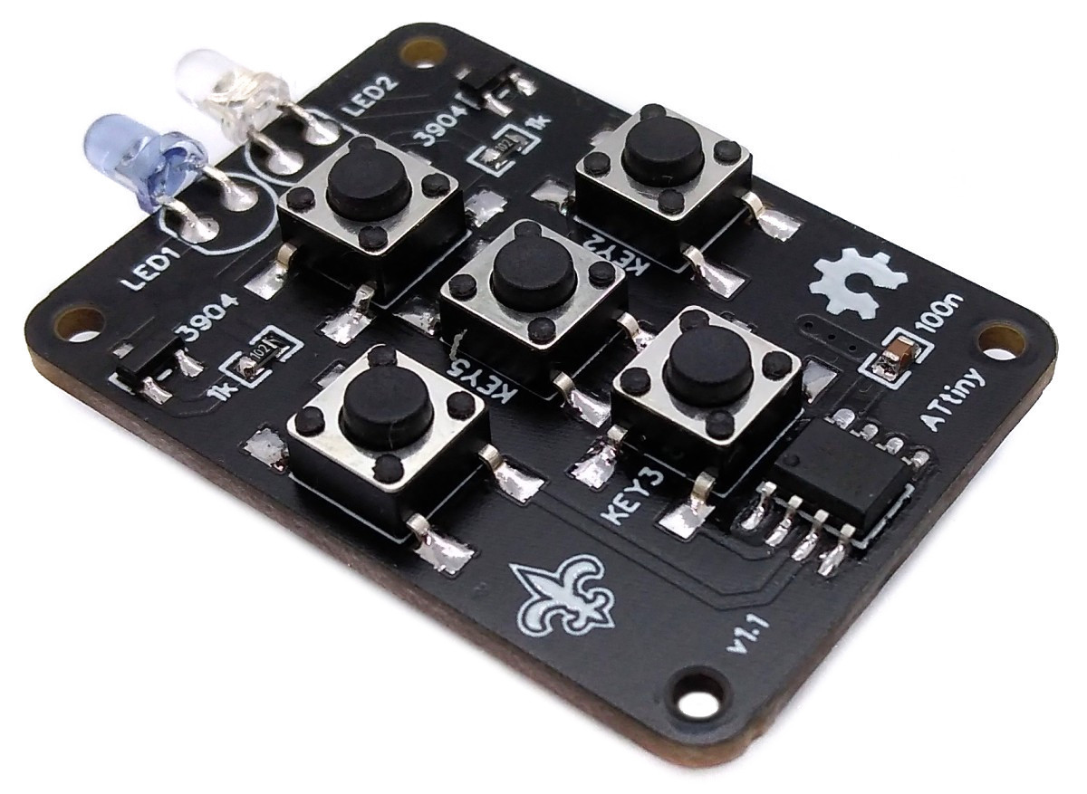
TinyRemote is a 5-button IR remote control based on an ATtiny13A powered by a CR2032 or LIR2032 coin cell battery.
- Project Video (YouTube): https://youtu.be/ad3eyNCov9c
- Design Files (EasyEDA): https://easyeda.com/wagiminator/attiny13-tinyremote
For the 12-button version of the ATtiny13A-based IR remote control see TinyRemoteXL.
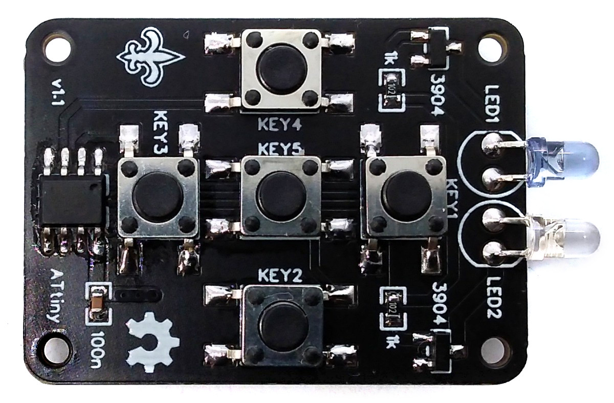
Hardware
The wiring is pretty simple:
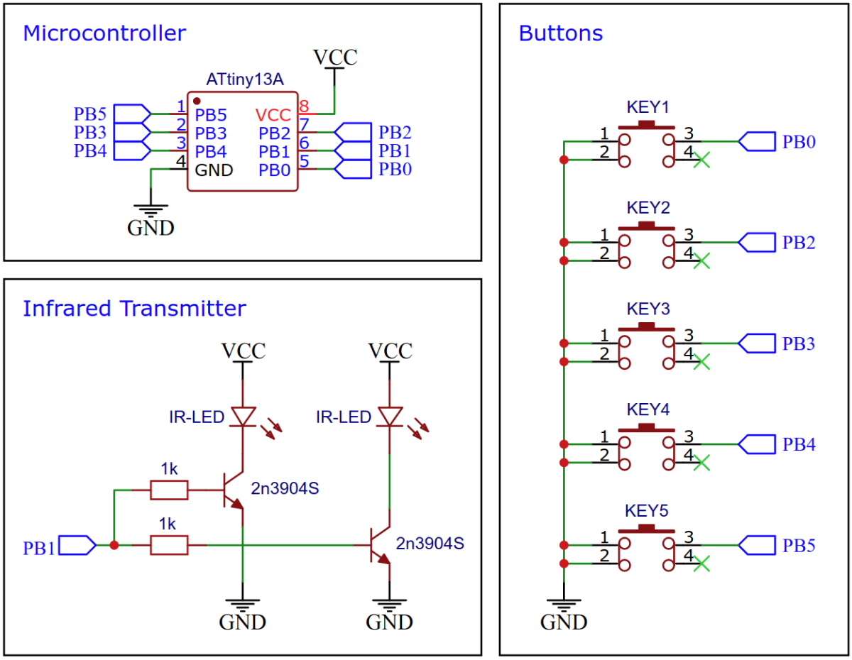
Due to the control with a high-frequency PWM, no series resistor is necessary for the LEDs. If you want to use only four buttons, you can leave KEY5 unsoldered and upload the 4-button version of the firmware. If you want to use all five buttons, you have to disable RESET on PB5 by burning the respective fuses after uploading the 5-button version of the firmware:
avrdude -c usbasp -p t13 -U lfuse:w:0x2a:m -U hfuse:w:0xfe:m
Warning: You will need a high voltage fuse resetter to undo this change!
For a simple breadboard test you can directly connect an IR LED via a 220 Ohm resistor to PB1.
Software
There are a variety of communication protocols for infrared remote controls. Basically, most of them have in common that a carrier wave between 30kHz and 58kHz, depending on the protocol, is generated by means of PWM at the IR diode so that the receiver can distinguish the signal from the noise. The IR telegram is modulated onto the carrier wave using pulse code modulation (PCM) by simply switching the IR LED on and off in a defined pattern. The telegrams are composed of a start frame, the device address of the receiver and the key-dependent command. The three most widely used protocols are implemented for the TinyRemote:
| Protocol | Carrier Frequency | Encoding Method | Start Frame | Address | Command |
|---|---|---|---|---|---|
| NEC | 38kHz | Pulse Distance | 9ms burst / 4.5ms space | 8/16 bits | 8 bits |
| RC-5 | 36kHz | Manchester | Start bits | 5 bits | 6/7 bits |
| Sony SIRC | 40kHz | Pulse Length | 2.4ms burst / 0.6ms space | 5/8/13 bits | 7 bits |
Since the software implementation for all protocols is very similar, only the NEC protocol is explained in more detail below.
Implementation of the NEC Protocol
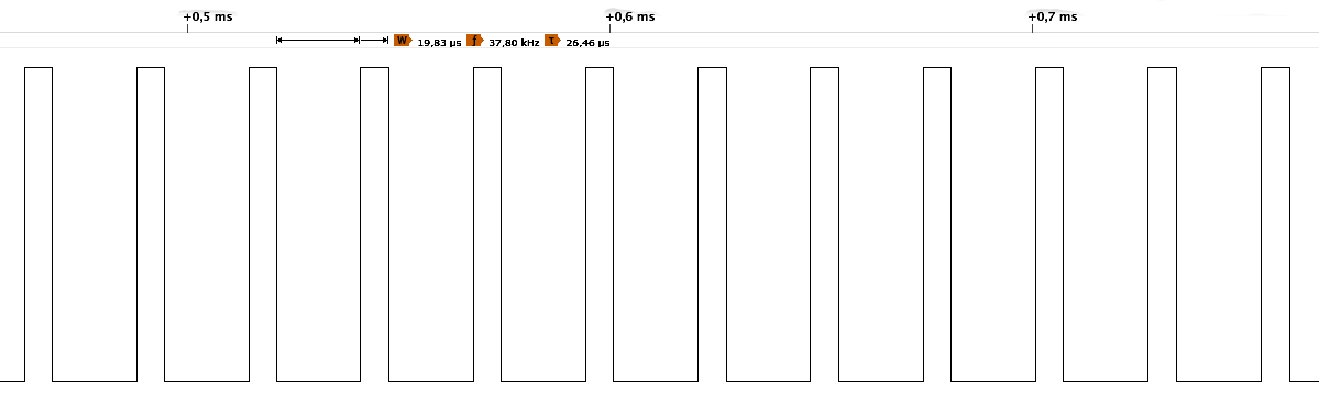
Timer0 generates the 38kHz carrier frequency with a duty cycle of 25% on the output pin to the IR LED.
// define values for 38kHz PWM frequency and 25% duty cycle
#define TOP   31          // 1200kHz / 38kHz - 1 = 31
#define DUTY  7           // 1200kHz / 38kHz / 4 - 1 = 7

// set timer0 to toggle IR pin at 38 kHz
TCCR0A = 0b00100011;      // PWM on OC0B (PB1)
TCCR0B = 0b00001001;      // no prescaler
OCR0A  = TOP;             // 38 kHz PWM frequency
OCR0B  = DUTY;            // 25 % duty cycle
Here's the result, captured with a logic analyzer:
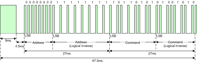
The IR telegram is modulated by toggling the pin of the IR LED to input or output. Setting the pin to output enables the PWM on this pin and sends a burst of the carrier wave. Setting the pin to input turns off the LED completely. The NEC protocol uses pulse distance encoding, which means a data bit is defined by the time between the bursts. A "0" bit is a 562.5µs burst (LED on: 38kHz PWM) followed by a 562.5µs space (LED off), a "1" bit is a 562.5µs burst followed by a 1687.5µs space.
An IR telegram starts with a 9ms leading burst followed by a 4.5ms space. Afterwards 4 data bytes are transmitted, least significant bit first. A final 562.5µs burst signifies the end of the transmission. The four data bytes are in order:
- the 8-bit address for the receiving device,
- the 8-bit logical inverse of the address,
- the 8-bit command and
- the 8-bit logical inverse of the command.
// macros to switch on/off IR LED
#define IRon()   DDRB |= 0b00000010   // PB1 as output = IR at OC0B (38 kHz)
#define IRoff()  DDRB &= 0b11111101   // PB1 as input  = LED off

// macros to modulate the signals according to NEC protocol with compensated timings
#define startPulse()    {IRon(); _delay_us(9000); IRoff(); _delay_us(4500);}
#define normalPulse()   {IRon(); _delay_us( 562); IRoff(); _delay_us( 557);}
#define bit1Pause()     _delay_us(1120) // 1687.5us - 562.5us = 1125us

// send a single byte via IR
void sendByte(uint8_t value) {
  for (uint8_t i=8; i; i--, value>>=1) {  // send 8 bits, LSB first
    normalPulse();                        // 562us burst, 562us pause
    if (value & 1) bit1Pause();           // extend pause if bit is 1
  }
}

// send complete telegram (start frame + address + command) via IR
void sendCode(uint8_t cmd) {
  startPulse();       // signify start of transmission
  sendByte(ADDR);     // send address byte
  sendByte(~ADDR);    // send inverse of address byte
  sendByte(cmd);      // send command byte
  sendByte(~cmd);     // send inverse of command byte
  normalPulse();      // signify end of transmission
}
The Extended NEC protocol uses 16-bit addresses. Instead of sending an 8-bit address and its logically inverse, first the low byte and then the high byte of the address is transmitted.
// send complete telegram (start frame + address + command) via IR (Extended NEC)
void sendCode(uint8_t cmd) {
  startPulse();           // signify start of transmission
  sendByte(ADDR & 0xFF);  // send address low byte
  sendByte(ADDR >> 8);    // send address high byte
  sendByte(cmd);          // send command byte
  sendByte(~cmd);         // send inverse of command byte
  normalPulse();          // signify end of transmission
}
Here's the result, captured with a logic analyzer:
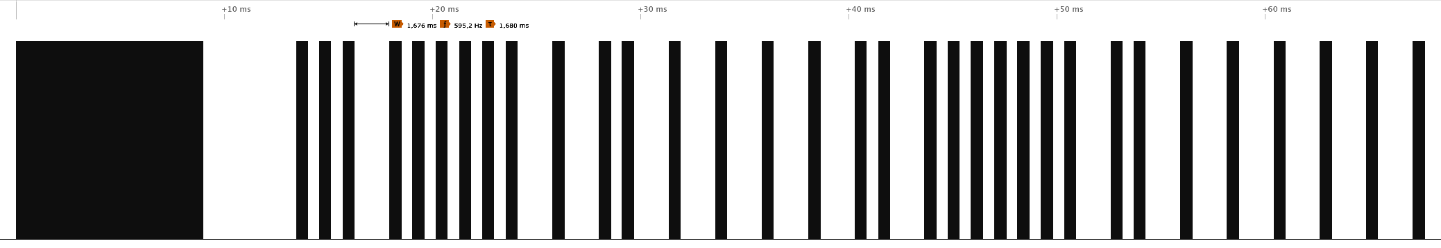
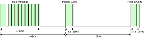
If the key on the remote controller is kept depressed, a repeat code will be issued consisting of a 9ms leading burst, a 2.25ms pause and a 562.5µs burst to mark the end. The repeat code will continue to be sent out at 108ms intervals, until the key is finally released.
// macros to modulate the signals according to NEC protocol with compensated timings
#define repeatPulse()   {IRon(); _delay_us(9000); IRoff(); _delay_us(2250);}
#define repeatCode()    {_delay_ms(40); repeatPulse(); normalPulse(); _delay_ms(56);}

// send repeat command until button is released
while (~PINB & 0b00111101) repeatCode();
The main loop of the implementation is pretty simple:
// IR codes (use 16-bit address for extended NEC protocol)
#define ADDR  0x04  // Address: LG TV
#define KEY1  0x02  // Command: Volume+
#define KEY2  0x00  // Command: Channel+
#define KEY3  0x03  // Command: Volume-
#define KEY4  0x01  // Command: Channel-
#define KEY5  0x08  // Command: Power

// main loop
while(1) {
    sleep_mode();                             // sleep until button is pressed
    _delay_ms(1);                             // debounce
    uint8_t buttons = ~PINB & 0b00111101;     // read button pins
    switch (buttons) {                        // send corresponding IR code
      case 0b00000001: sendCode(KEY1); break;
      case 0b00000100: sendCode(KEY2); break;
      case 0b00001000: sendCode(KEY3); break;
      case 0b00010000: sendCode(KEY4); break;
      case 0b00100000: sendCode(KEY5); break;
      default: break;
    }
}
Implementation of the Philips RC-5 Protocol
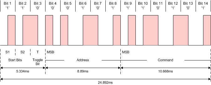
The Philips RC-5 protocol uses Manchester encoding on a carrier frequency of 36kHz. A "0" bit is an 889µs burst followed by an 889µs space, a "1" bit is an 889µs space followed by an 889µs burst. An IR telegram starts with two start bits. The first bit is always "1", the second bit is "1" in the original protocol and the inverted 7th bit of the command in the extended RC-5 protocol. The third bit toggles after each button release. The next five bits represent the device address and the last six bits represent the command, all transmitted MSB first.
As long as a key remains down the telegram will be repeated every 114ms without changing the toggle bit.
// define values for 36kHz PWM frequency and 25% duty cycle
#define TOP   32                      // 1200kHz / 36kHz - 1 = 32
#define DUTY  7                       // 1200kHz / 36kHz / 4 - 1 = 7

// macros to switch on/off IR LED
#define IRon()   DDRB |= 0b00000010   // PB1 as output = IR at OC0B (36 kHz)
#define IRoff()  DDRB &= 0b11111101   // PB1 as input  = LED off

// macros to modulate the signals according to RC-5 protocol with compensated timings
#define bit0Pulse()     {IRon();  _delay_us(889); IRoff(); _delay_us(884);}
#define bit1Pulse()     {IRoff(); _delay_us(889); IRon();  _delay_us(884);}
#define repeatDelay()   _delay_ms(89) // 114ms - 14 * 2 * 889us

// bitmasks
#define startBit  0b0010000000000000
#define cmdBit7   0b0001000000000000
#define toggleBit 0b0000100000000000

// toggle state variable
uint8_t toggle = 0;

// send complete telegram (startbits + togglebit + address + command) via IR
void sendCode(uint8_t cmd) {
  // prepare the message
  uint16_t message = ADDR << 6;         // shift address to the right position
  message |= (cmd & 0x3f);              // add the low 6 bits of the command
  if (~cmd & 0x40) message |= cmdBit7;  // add inverse of 7th command bit
  message |= startBit;                  // add start bit
  if (toggle) message |= toggleBit;     // add toggle bit

  // send the message
  do {
    uint16_t bitmask = startBit;        // set the bitmask to first bit to send
    for(uint8_t i=14; i; i--, bitmask>>=1) {                // 14 bits, MSB first
      (message & bitmask) ? (bit1Pulse()) : (bit0Pulse());  // send the bit
    }
    IRoff();                            // switch off IR LED
    repeatDelay();                      // wait for next repeat
  } while(~PINB & 0b00111101);          // repeat sending until button is released
  toggle ^= 1;                          // toggle the toggle bit
}
Implementation of the Sony SIRC Protocol
The Sony SIRC protocol uses pulse length encoding on a carrier frequency of 40kHz. A "0" bit is a 600µs burst followed by a 600µs space, a "1" bit is a 1200µs burst followed by a 600µs space. An IR telegram starts with a 2400µs leading burst followed by a 600µs space. The command and address bits are then transmitted, LSB first. Depending on the protocol version, these are in detail:
- 12-bit version: 7 command bits, 5 address bits
- 15-bit version: 7 command bits, 8 address bits
- 20-bit version: 7 command bits, 5 address bits, 8 extended bits
As long as a key remains down the telegram will be repeated every 45ms.
// define values for 40kHz PWM frequency and 25% duty cycle
#define TOP   29                      // 1200kHz / 40kHz - 1 = 29
#define DUTY  7                       // 1200kHz / 40kHz / 4 - 1 = 7

// macros to switch on/off IR LED
#define IRon()   DDRB |= 0b00000010   // PB1 as output = IR at OC0B (40kHz)
#define IRoff()  DDRB &= 0b11111101   // PB1 as input  = LED off

// macros to modulate the signals according to SONY protocol with compensated timings
#define startPulse()    {IRon(); _delay_us(2400); IRoff(); _delay_us( 595);}
#define bit0Pulse()     {IRon(); _delay_us( 600); IRoff(); _delay_us( 595);}
#define bit1Pulse()     {IRon(); _delay_us(1200); IRoff(); _delay_us( 595);}
#define repeatPause()   _delay_ms(27)


// send "number" of bits of "value" via IR
void sendByte(uint8_t value, uint8_t number) {
  do {                                    // send number of bits, LSB first
    (value & 1) ? (bit1Pulse()) : (bit0Pulse());  // send bit
    value>>=1;                            // next bit
  } while(--number);
}

// send complete telegram (start frame + command + address) via IR
void sendCode(uint8_t cmd) {
  do {
    startPulse();               // signify start of transmission
    sendByte(cmd, 7);           // send 7 command bits
    #if BITS == 12              // if 12-bit version:
      sendByte(ADDR, 5);        // send 5 address bits
    #elif BITS == 15            // if 15-bit version:
      sendByte(ADDR, 8);        // send 8 address bits
    #elif BITS == 20            // if 20-bit version:
      sendByte(ADDR, 5);        // send 5 address bits
      sendByte(EXTB, 8);        // send 8 extended bits
    #endif
    repeatPause();              // wait until next repeat
  } while (~PINB & 0b00011101); // repeat sending until button is released
}
Power Saving
The code shuts down unused peripherals and utilizes the sleep mode power down function. It wakes up on every button press by pin change interrupt.
// setup pin change interrupt
GIMSK = 0b00100000;                   // turn on pin change interrupts
PCMSK = 0b00111101;                   // turn on interrupt on button pins
SREG |= 0b10000000;                   // enable global interrupts

// disable unused peripherals and set sleep mode to save power
ADCSRA = 0b00000000;                  // disable ADC
ACSR   = 0b10000000;                  // disable analog comperator
PRR    = 0b00000001;                  // shut down ADC
set_sleep_mode(SLEEP_MODE_PWR_DOWN);  // set sleep mode to power down
As long as no button is pressed, the ATtiny remains in sleep mode power down and consumes a current of around 150nA at a voltage of 3V. The typical capacity of a CR2032 battery is 230mAh. This results in a theoretical battery life of 1.5 million hours or 179 years. In real life, of course, no battery will last that long due to its self-discharge. When the button is pressed, peaks of up to 30mA are consumed. The diagram below shows the course of the current consumption when a button is pressed and a NEC telegram is sent according to a measurement with the Power Profiler Kit II:
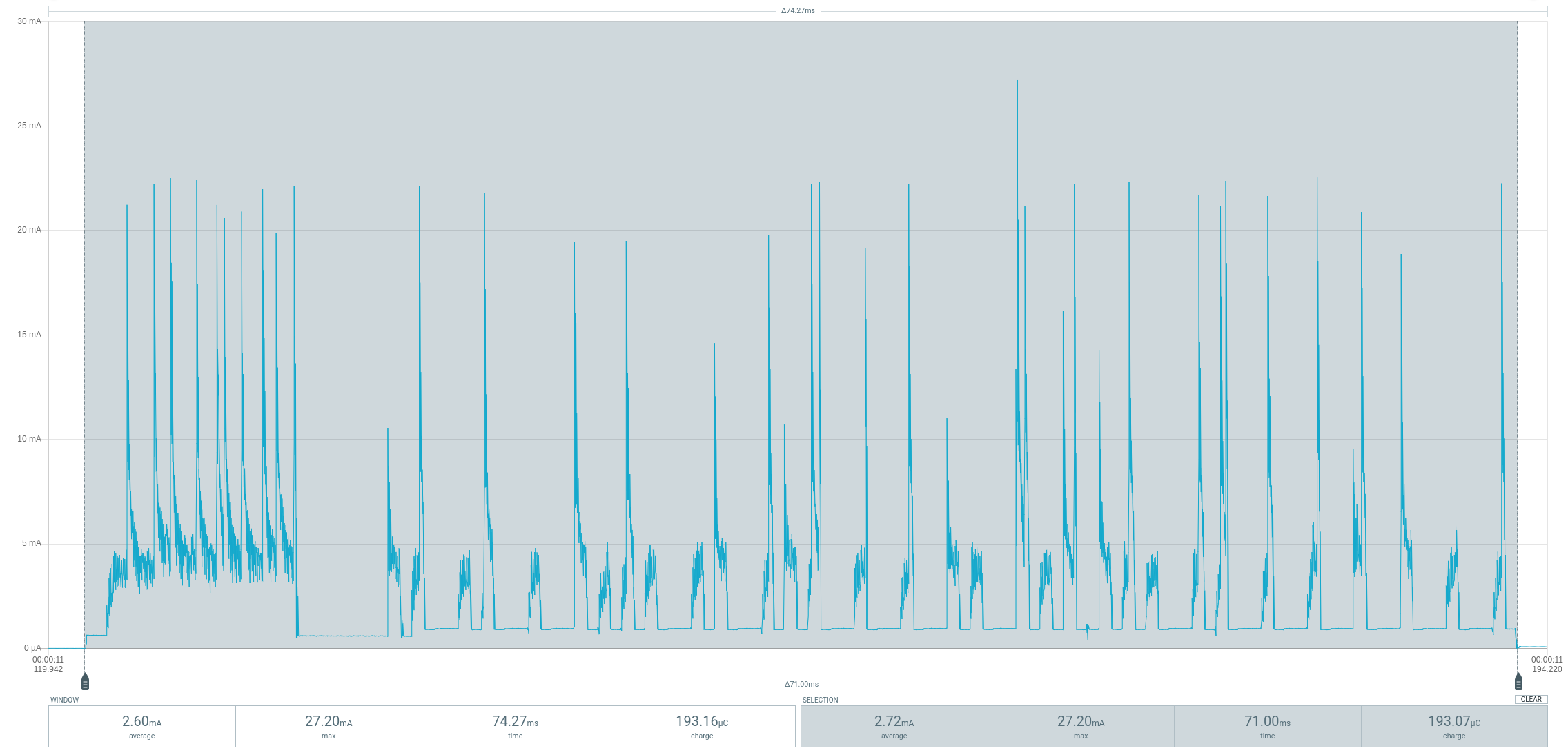
When sending a NEC telegram, the current requirement increases to an average of around 2.75mA for 71ms. Theoretically, over 4 million telegrams could be sent with one battery. Note that the rechargeable LIR2032 batteries have a significantly lower capacity.
Timing Accuracy
The accuracy of the internal oscillator of the ATtiny13 is +/-10% with the factory calibration. Usually this is sufficient for an infrared remote control. Slight deviations in timing are tolerated by the receiver, since cheap remote controls are usually not more accurate. Nevertheless, it certainly doesn't hurt to manually calibrate the internal oscillator and set the corresponding OSCCAL value at the beginning of the code.
// oscillator calibration value (uncomment and set if necessary)
#define OSCCAL_VAL  0x48
References, Links and Notes
- IR remote control explanations by San Bergmans
- IR remote control by Christoph Niessen (german)
- IR remote control detective by David Johnson-Davies
- Infrared communication concepts (altium.com)
- NEC decoder based on ATtiny13A
- TinyRemote XL
- TinyRemote RF
- OSC Calibrator
- ATtiny13A datasheet
License

This work is licensed under Creative Commons Attribution-ShareAlike 3.0 Unported License. (http://creativecommons.org/licenses/by-sa/3.0/)
