Arduino FOC Balancer Save
Modular Arduino two wheel balancing robot based on gimbal BLDC motors and simplefoc library
Arduino SimpleFOCBalancer
Modular Arduino two wheel balancing robot based on gimbal BLDC motors and SimpleFOClibrary.

Balancing robots are always a bit tricky to design, in order to make the robot balance we need to design and tune our mechanical structure and the control algorithm and, in the same time, choose optimal motors, sensors and microcontrollers. Therefore, even though BLDC motors are a great choice for balancing robots the complexity of their control made them undesirable. So this robot is an attempt to create a simple and modular, BLDC motor based, balancing robot that can be easily adapted for different motor+sensor+mcu+driver combinations and to show off the power and the awesome dynamics of gimbal BLDC motors 😄
YouTube video demo

Readme structure
Mechanical components

3D printed parts
This balancer project has 5 3d printed parts. You can find them in the CAD > STL directory. They are:
- center frame (
FOC_balancer.stl)- infill:
30% - layer hight:
>0.15mm
- infill:
- wheels (
wheel.stl)- infill:
30% - layer hight:
0.1-0.15mm - reasonably precise
- infill:
- MCU mount (
arduino_holder.stl)- infill:
30% - layer hight:
>0.15mm
- infill:
- top plate (
top_plate.stl)- infill:
20% - layer hight:
>0.15mm
- infill:
I have printed the pendulum in the PLA filament but there should be no real difference in using PETG or ABS filaments, this is just what I had in hand at the moment.
You will also find all the CAD files used in this project in the CAD folder. I have included the Solidworks 2016 parts and the full assembly. Additionally all the parts are exported to STEP format for easier porting to the other CAD IDEs.
Beware: I have designed the holes on the pendulum arm and the wheel to match perfectly the motor the encoders I was using, so please check the dimensions of your motors and encoder holes before printing 😄 If you would prefer some other CAD format, let me know, maybe I can export it differently.
Hardware parts
The mechanical components you will need are two sets of screws which you can easily find in your hardware store and the RC car tires that can be bought in bulk online.
| Component | Description | Link | Price |
|---|---|---|---|
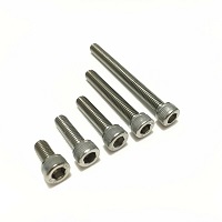 |
M3 screws 25pcs M3x10mm |
Ebay | 2$ |
|
M4 screws & nuts 2pcs M4x50mm |
Ebay | 4$ |
 |
RC wheel HSP HPI 8014 2pcs 69.5mmx29mm |
Aliexpress | 5$ |
Electrical components
BLDC motor
The BLDC motors I was using in my video are an old versions of the iPower GM4108 motors which are not available anymore, in any case I was not able to find a website that would sell them. The good news is that you can use basically any other gimbal motor in that class with only minor modifications, mostly in the CAD parts - change the mounting holes positions. Some of the motors I was able to find that would be the most similar to my motor would be:
| Component | Description | Link | Price |
|---|---|---|---|
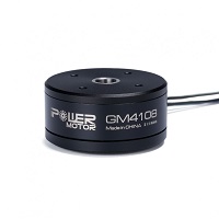 |
iPower Motor GM4108H-120T | iFlight webshop | 35$ |
 |
BGM4108-150HS | Ebay | 32$ |
Position sensors
In my case I was using two encoders for the two motors. Now, this is very specific to my particular implementation, with minor CAD modifications you can use any type of the position sensor that is supported by the SimpleFOClibrary. Click here to see the documentation of the supported sensors.
The encoders I have used in this project are:
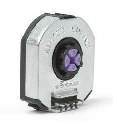 |
AMT103 CUI | Mouser | 20$ |
|---|
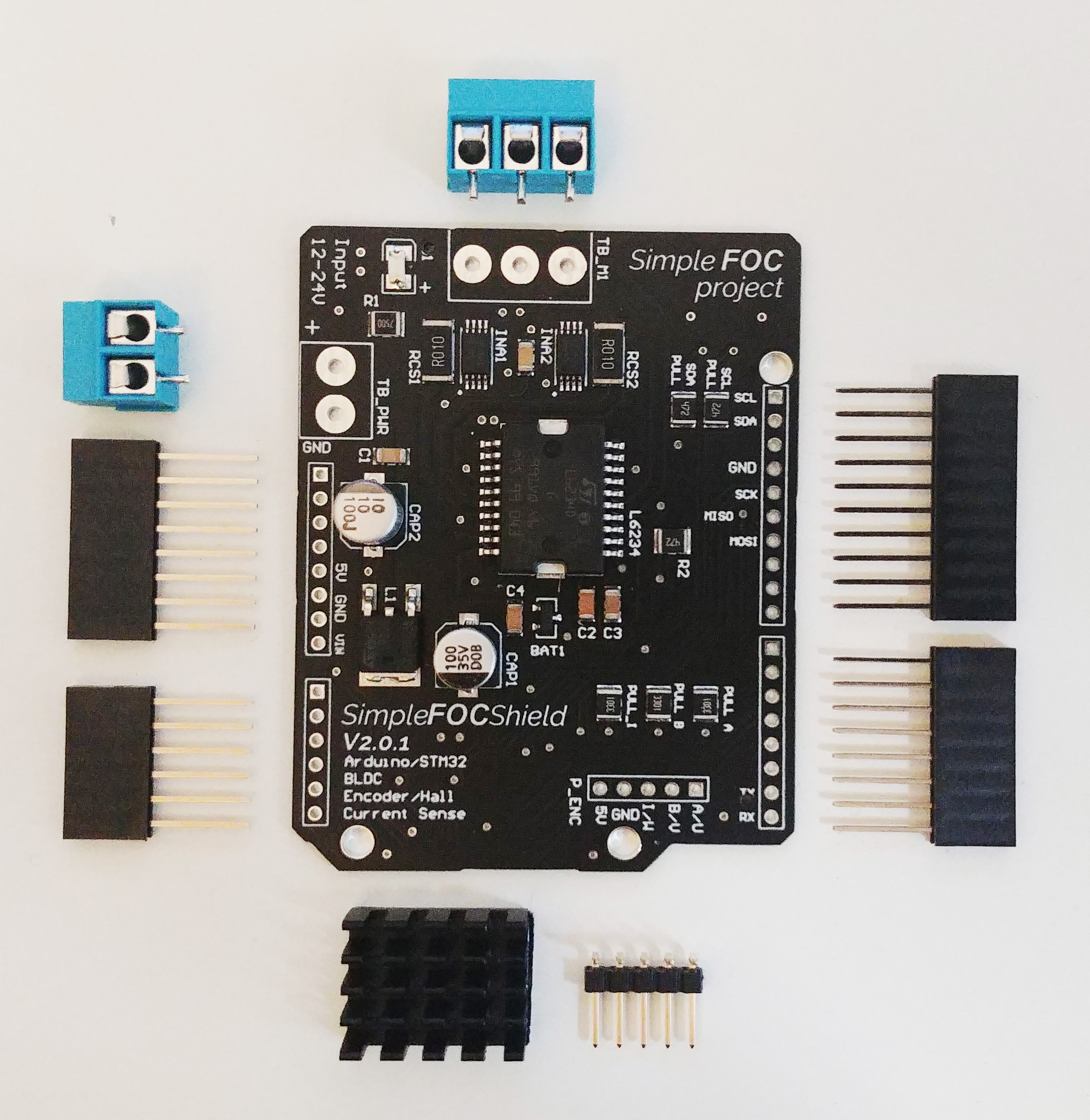
BLDC driver
In this project I used the SimpleFOCShield v2.0.3 which is basically an Arduino shield which enables the usage of the FOC algorithm with the BLDC motors. It is practically plug & play in combination with the Arduino SimpleFOClibrary.
But there is a lot of different boards that you can use to make this balancer. Basically any gimbal motor driver that is supported by the SimpleFOClibrary will be suitable. Click here to see the documentation of the supported drivers. Here are some examples of the possible BLDC drives you could use:
| Examples | Description | Link | Price |
|---|---|---|---|
 |
SimpleFOCShield v1/v2 | More info | 20$ |
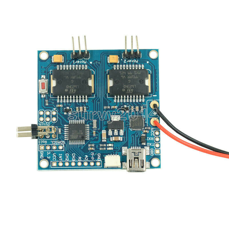 |
BGC 3.1 | More info | 10$ |
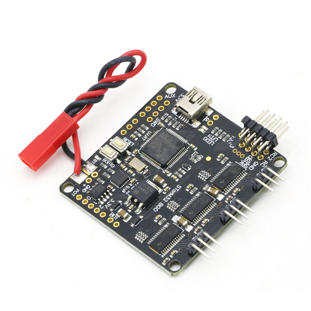 |
Storm32 BGC | Ebay | 25$ |
IMU module
I've used the IMU MPU6050 with integrated DMP. It is a great board, very cheap and very powerful. You can use any other accelerometer to make the balancing robot but you might need to do some coda adaptation, mostly in the imu_helpers.cpp/h.
| Examples | Description | Link | Price |
|---|---|---|---|
 |
MPU6050 | Amazon | 2-5$ |
Bluetooth module
If using the ESP32 based mcu you will not need an additional Bluetooth module. But if you decide to go with some other mcu, I advise you to use the HC-05/HC-06 modules, they are very simple to use and will work out of the box with the code.
| Examples | Description | Link | Price |
|---|---|---|---|
 |
HC-06 | Amazon | 2-10$ |
Microcontroller
In my example I've used EPS32 based microcontroller and the Stm32 based one but any type of the MCU that is supported by the SimpleFOClibrary will do. Click here to see the documentation of the supported microcontrollers.
| Examples | Description | Link | Price |
|---|---|---|---|
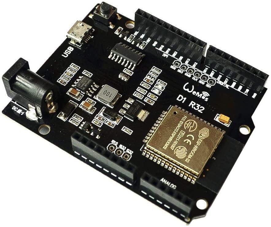 |
WeMos D1 R32 | More info | 10$ |
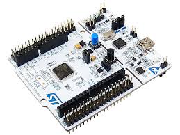 |
Nucleo-64 F411RE | More info | 15$ |
If using the gimbal controller boards such as BGC3.0/BGC3.1, Storm32 or similar you will do not bea able to change your microcontroller because it is integrated into the boards.
Arduino code
still not complete
Control algorithm
The control algorithm implemented in the Arduino sketch is very simple. It is a 2 PID controller cascade shown on the image bellow.

The PID stabilisation controller will make sure that any target angle that is defined by the PID velocity is reached as soon as possible. Where PID velocity will try to keep the balancer robot moving with desired velocity defined by the user. This simple scheme is very powerful because it will make the balancer stand still even if the balancer zero angle has some offset.
Here is the arduino code of the controller:
// read pitch from the IMU
float pitch = getPitchIMU();
// calculate the target angle for throttle control
float target_pitch = lpf_pitch_cmd(pid_vel((motor1.shaft_velocity + motor2.shaft_velocity) / 2 - lpf_throttle(throttle)));
// calculate the target voltage
float voltage_control = pid_stb(target_pitch - pitch);

// filter steering
float steering_adj = lpf_steering(steering);
// set the tergat voltage value
motor1.target = voltage_control + steering_adj;
motor2.target = voltage_control - steering_adj;
The balancer velocity is estimated as average velocity for each wheel separately (motor1.shaft_velocity + motor2.shaft_velocity) / 2. The target velocity is defined by the throttle variable set by the user. In addition to the throttle user can set the steering variable which will determine turning rate of the robot. The units of the steering variable are Volts in the provided example.
The PID parameters and filtering values can be changed by changing the definition of the pid_stb and pid_vel:
// control algorithm parameters
// stabilisation pid
PIDController pid_stb{.P = 30, .I = 100, .D = 1, .ramp = 100000, .limit = 7};
// velocity pid
PIDController pid_vel{.P = 0.01, .I = 0.03, .D = 0, .ramp = 10000, .limit = _PI / 10};
// velocity control filtering
LowPassFilter lpf_pitch_cmd{.Tf = 0.07};
// low pass filters for user commands - throttle and steering
LowPassFilter lpf_throttle{.Tf = 0.5};
LowPassFilter lpf_steering{.Tf = 0.1};
Bluetooth remote control
For remote controlling your robot you can use any wireless communication you wish. In my case I've used bluetooth with mobile joystick app. There is really a lot of them and you can choose the one that you prefer. In my case I've used an app called Gibalo. Link to the google play app

Regardless of the communication protocol that you choose to use the only three variables that you need to change in the balancer code are
-
throttle- target velocity of the balancer: value [-max_throttle,max_throttle] -
steering- turning rate command: value [-max_steering,max_steering] -
state-1on,0off
For the Gibalo app the Arduino code will be:
/**
  Function intended for connecting to the Gibalo application
  In one byte it receives either throttle or steering command
  - if received byte  in range [0,200] then throttle command in between [-100, 100]
  - if received byte  in range [210,250] then steering command in between [-20, 20]
*/
void handleBluetooth(Stream& bt_port) {
  int inByte;
  if (bt_port.available() > 0) {
    while (bt_port.available()) {
      inByte = bt_port.read();
    }
    inByte = inByte - 100;
    if (inByte == 155) {
      // ON Byte
      steering = 0;
      throttle = 0;
      state = 1;
      bt_port.println("State ON");
    } else if (inByte == 154) {
      // OFF Byte
      steering = 0;
      throttle = 0;
      state = 0;
      bt_port.println("State OFF");
    } else if (inByte >= -100 && inByte <= 100) {
      // throttle set-point Byte
      throttle = max_throttle *  ((float)inByte) / 100.0;
    } else if (inByte >= 110 && inByte <= 150) {
      // steering set-point Byte
      steering = max_steering * ((float)(inByte - 130.0)) / 20.0;
    } else {
      // Error Byte
      steering = 0;
      throttle = 0;
      bt_port.println("Error number!");
    }
    bt_port.flush();
  }
}
