Raspberry Pi 1u Server Save
A low power 1U Raspberry Pi cluster server for inexpensive colocation.
Raspberry Pi 1U Server
There are server colocation providers that allow hosting a 1U server for as low as $30/month, but there's a catch: There are restrictions on power usage (1A @ 120v max, for example) because they're expecting small and power-efficient network equipment like firewalls.
This repo is about designing a server that fits within the 1U space and 1A @ 120v power constraint while maximizing computing power, storage, and value.
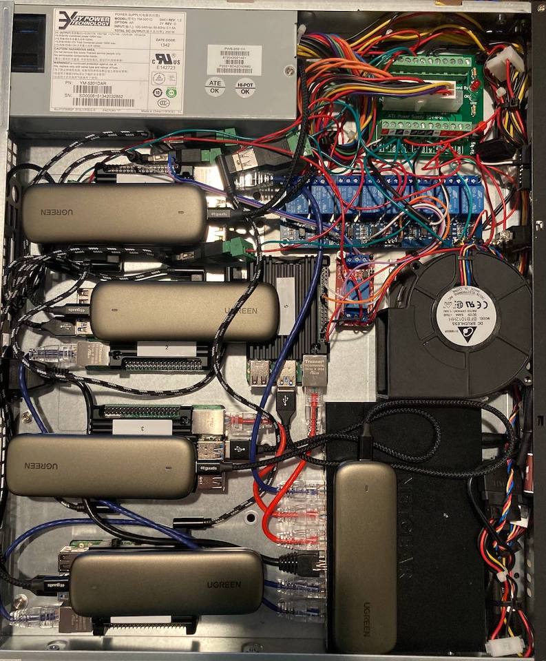
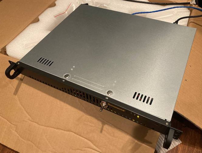
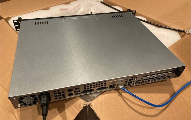
Table of contents
- Colocation Providers
- Parts
- Power Usage
- Software Setup
- Hardware Setup
- Network Setup
- Remote Power Management Software
- Measuring Amperage
- Single Points Of Failure
- How Many More Pi's Will Fit?
- Cloud Comparisons
- Physical Server Comparisons
- Ideas For V2
- Similar Projects
Colocation Providers
-
$29.95/month - Nextarray- Went out of business and ended up getting taken over by another company.
-
100Mbps Unmetered -
1 Amps 120V -
3 Usable IPs (+$13 for 11 usable IPs) -
GigE Port -
1.5Tbps Protection -
Location: Dallas, TX
- $30/month - Turnkey Internet
- 1 Amp @ 120V
- 1 Usable IP (+$10 for 5 usable IPs)
- 10 Mbit Ethernet
- 3 TB Monthly Transfer
- $50/month - Joe’s Datacenter
- 5 Usable IPs
- Bandwidth: 33TB on 1Gbps Port
- Power: Up To 2 Amps 120V (Single Power Connection)
- Network Connection: Single Network Cable
- Location: Kansas City, MO
Parts
Specs Summary
- 20x 1.5GHz CPU cores
- 16GB LPDDR4-3200 SDRAM
- 1.2TB SSD Storage
- Gigabit Ethernet
Total cost: ~$800
1U Chassis
- $85 - Supermicro SuperChassis 1U Rackmount Server Case CSE-512L-200B
- $36.34 - Server Rack Rails
- Depending on the colocation place, these may be provided for free.
Storage
- 5x $34.99 - Kingston A400 240G Internal SSD M.2
- Need to use M.2 drives to save space.
- SSDs are more also usually more durable and faster than USB drives and SD cards.
- 1x $31.50 - 5-Pack of SAMSUNG 32GB Evo Plus Micro SD Cards
- For failover storage in case the SSD fails.
Storage Enclosure
Switch
- $19.99 - NETGEAR 8-Port Gigabit Ethernet Unmanaged Switch (GS308)
- 12v, so can use the ATX power supply easily.
- Using an unmanaged switch due to a limited number of IP addresses, and to make a firewall and router for a private network unnecessary.
Single Board Computer
- 5x $35 - Raspberry Pi 4b
- Best software support and battle-tested design.
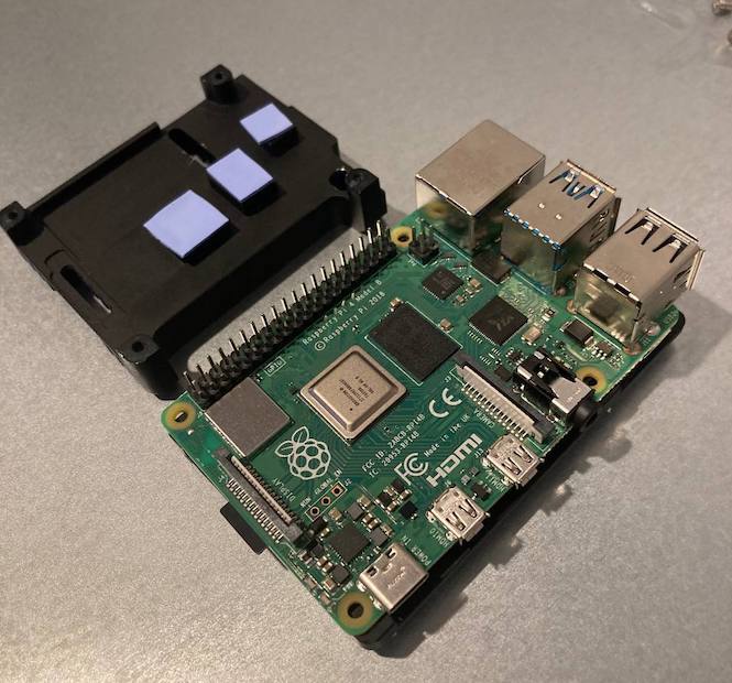
Raspberry Pi Case
- 5x $12.99 - Geekworm Raspberry Pi 4 Armor Case
- Allows access to GPIO pins, which will be necessary for the Pi wired to the relay for remote power management.
- Uses less space than the Flirc case, which makes it difficult to close the chassis lid.
- Reviews: 1
Power
- $12.99 - ATX breakout board
- $11.88 - Standoffs for ATX breakout board
- 3x $7.99 - USB 2.0 Female Screw Terminal Block Connector, 2-Pack for wiring USB cables to the breakout board
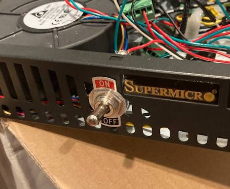
- $8.90 - Toggle switch for powering off the server from the front panel.
Remote Power Management
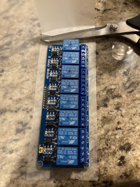
- $8.99 - 8 Channel DC 5V Relay Module
- For power cycling most of the Pi's remotely.
- $5.98 - 1 Channel Relay Module
- For power cycling the Pi that controls the 8 channel relay.
Other Wiring
- $8.99 - Ethernet Extension Cable w/ screws
- For adding a single ethernet port to the back of the chassis that connects to the switch.
- $26.99 - Kill A Watt Electricity Usage Monitor
- For measuring amperage and ensuring it's below the max.
- $20.95 - Noctua NA-FC1, 4-Pin PWM Fan Controller
- For controlling the chassis blower fan without a motherboard.
- 2x $6.99 - 2-pack of 1ft USB C Cables
- $14.99 - USB C Cables w/ right angle connectors, 6-pack
- The right angle connector is key, this saves a ton of space.
- 4x $2.09 - 1 Foot Long Slim Ethernet cables
- 1x $2.09 - 0.5 Foot Long Slim Ethernet cables
- $8.99 - Zip Tie Mounts
- $10.99 - Mounting tape
- $5.28 - 22 AWG Stranded Copper Wire
Power Usage
- Raspberry Pi 4 + SSD:
- idle: 2.2W, 0.44A @ 5V (0.018A @ 120v)
- load: 4.2W, 0.84A @ 5V (0.035A @ 120v)
- Total w/ blower fan on low setting:
- idle: 36-38.4W, 0.30-32A @ 120V
- load: 43.2W, 0.36A @ 120V
- Total w/ blower fan on high setting:
- idle: 48W, 0.4A @ 120V
Software Setup
You will need to do this for each of the Raspberry Pi's:
-
Flash an SD card with Raspbian Lite (under "Raspberry Pi OS (other)" in the Raspberry Pi Imager) and enable SSH with:
-
cd /Volumes/boot/ -
touch ssh
-
- Insert the SD card into the Pi, power on, and ssh into the Pi with
ssh pi@<ip address>and the password "raspberry". - Update the hostname to correspond to the number on the case:
-
sudo raspi-config -
1 System Options->S4 Hostname-> Update hostname -> Finish -> Reboot
-
- Update the firmware on the Pi to allow booting from USB:
-
sudo apt-get update && sudo apt full-upgrade -y -
sudo rpi-update(only do this once on each Pi)
-
- Disable HDMI to save power:
sudo sed -i -e '$i \/usr/bin/tvservice -o\n' /etc/rc.local - Disable avahi (used for making raspberrypi.local work on a local network):
-
sudo systemctl stop avahi-daemon.service -
sudo systemctl stop avahi-daemon.socket -
sudo systemctl disable avahi-daemon.service -
sudo systemctl disable avahi-daemon.socket
-
-
Disable wifi and bluetooth:
-
sudo bash -c 'echo -e "dtoverlay=pi3-disable-wifi" >> /boot/config.txt' -
sudo bash -c 'echo -e "dtoverlay=pi3-disable-bt" >> /boot/config.txt' -
sudo reboot
-
-
Add your public key (while disconnected from the pi, with
ssh-copy-id pi@<IP-ADDRESS>) - Make sure the SSD is plugged into one of the blue USB 3 ports.
- SSH into the Pi again and Disable password authentication:
-
sudo sed -i '/^#*PubkeyAuthentication /c PubkeyAuthentication yes' /etc/ssh/sshd_config -
sudo sed -i '/^#*ChallengeResponseAuthentication /c ChallengeResponseAuthentication no' /etc/ssh/sshd_config -
sudo sed -i '/^#*PasswordAuthentication /c PasswordAuthentication no' /etc/ssh/sshd_config -
sudo sed -i '/^#*UsePAM /c UsePAM no' /etc/ssh/sshd_config
-
- Configure the Pi to prioritize booting from the SSD:
-
sudo raspi-config -
6 Advanced Options->A6 Boot Order->B2 USB Boot-> Finish -> Reboot - If you see an "No EEPROM bin file found" error, you may need to run
sudo -E rpi-eeprom-config --editand add[all] BOOT_ORDER=0xf14.
-
- Repeat the steps above (without
sudo rpi-update) with the new OS on the SSD. SSH'ing into the new OS on the SSD may require clearing out the line with the corresponding IP in your~/.ssh/known_hostsfile withssh-keygen -R <host>.
Hardware Setup
-
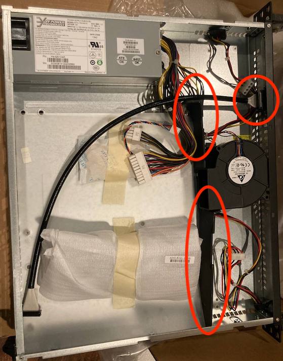
Remove the hard drive bay dividers and front panel extension cable from the inside of the chassis.
-
Install the Raspberry Pi's into their cases.
-
Install the M.2 drives into their enclosures.
-
Insert a SD card into each of the Pi's.
-
Follow the Software Setup guide if you haven't already.
-
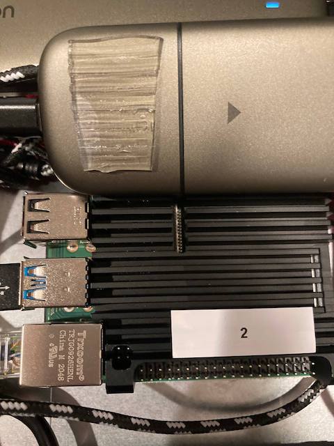
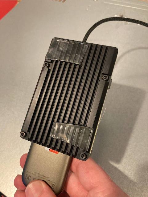
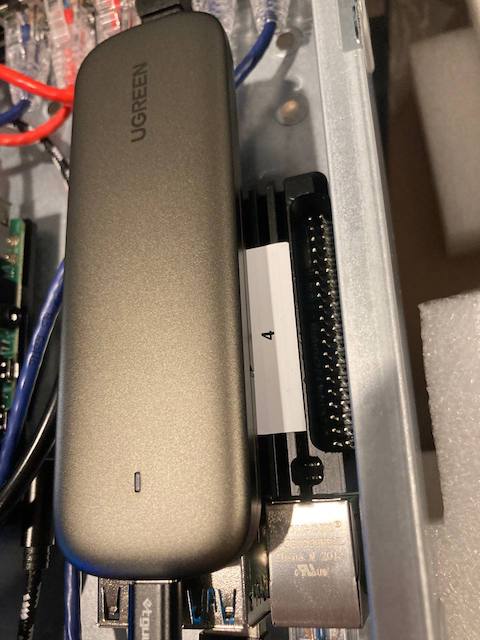
Add mounting tape to the bottom of each of the SSD enclosures and attach them to the top of the Raspberry Pi's.
-
Add mounting tape to the bottom of the raspberry pi cases. Don't remove the bottom cover of the mounting tape adhesive yet.
-
Remove the rubber feet from the bottom of the networking switch and replace with 4x small squares of mounting tape. Don't remove the bottom cover of the mounting tape adhesive yet.
-
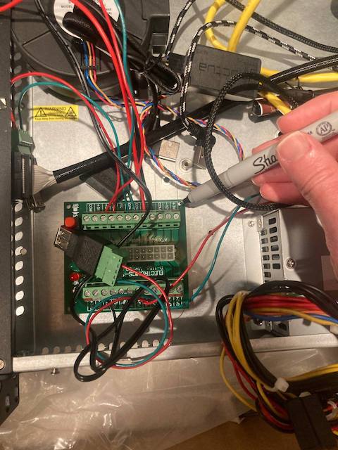
Add labels with numbers to the tops of the cases. These numbers will correspond to the hostnames of the Pi's in the software setup.
-
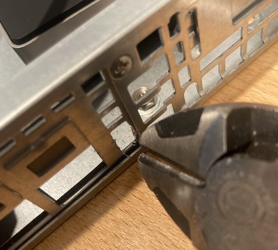
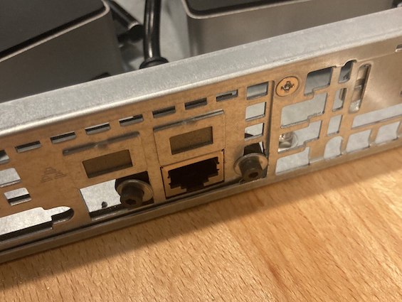
Use wire cutters to remove the metal adjacent to the ethernet port and mount the port side of the ethernet extension to the back of the chassis with washers and the included bolts.
-
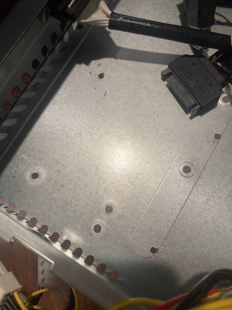
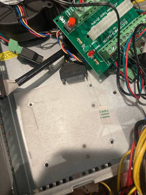
Cut a section of the plastic sheet that came with the chassis (for under the motherboard) to fit under the power supply breakout board.
-
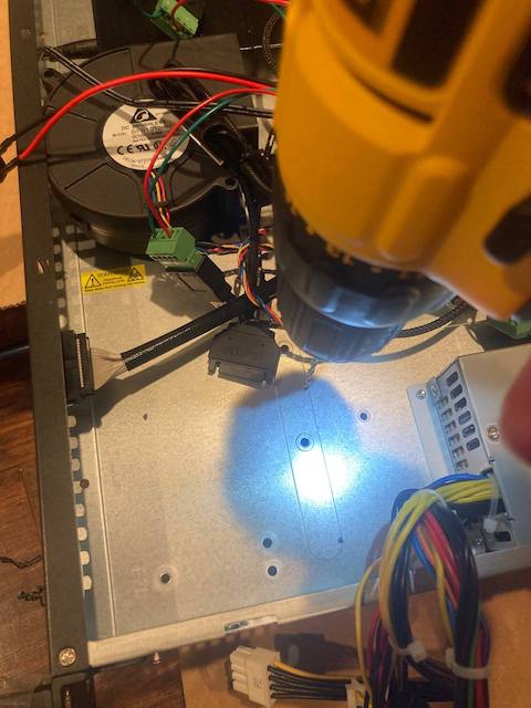
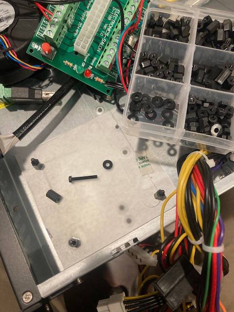
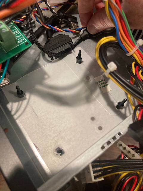
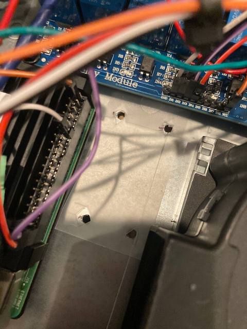
Drill holes in the chassis, insert nylon standoffs, and add the plastic sheet.
-
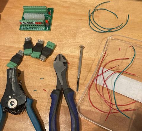
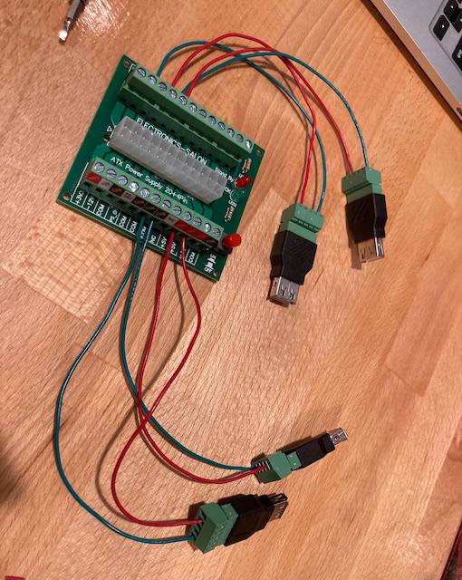
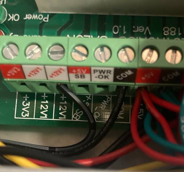
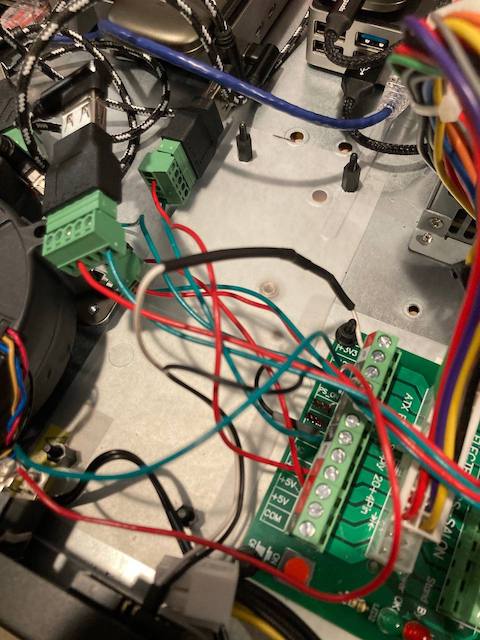
Cut 5x 6" lengths of red standed wire, strip the both ends, and install one end of each wire into the "+" slots of the USB terminal blocks and the other side of each wire into the 5V terminals of the ATX power supply breakout board. Make sure the 20 pin power supply has a corresponding wire, some wires will be missing and may not actually work on the power breakout board.
-
Cut and strip 5x 6" lengths of green standed wires then install one end of the each wire into the "-" slots of the USB terminal blocks and the other side of each wire into the COM terminals on the ATX power supply breakout board. Again, ensure the wire exists on the 20 pin cable before using the terminal block.
-
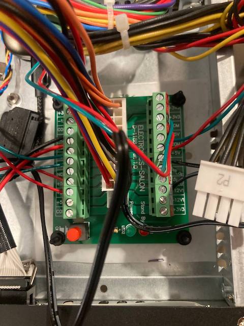
Mount the ATX power supply breakout board to the chassis and secure with nylon nuts. Insert the 20 pin ATX power supply connector into the ATX power supply breakout board.
-
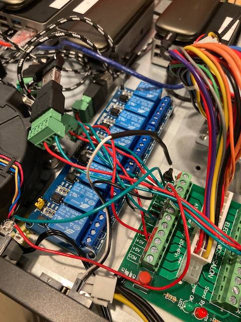
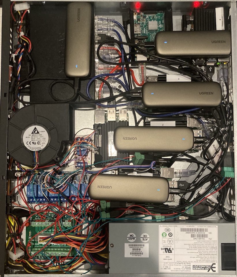
Remove the covers from the mounting tape adhesive on the bottom of the Pi cases and switch, then position them in the chassis. You will probably want to try to match the layout from the finished project above, but this may change depending on how many Raspberry Pi's you have.
-
Attach ethernet cables from each of the Raspberry Pi's to the networking switch.
-
Cut the 12V barrel connector along with 12" of wire off of the power adapter for the network switch. Attach the cable with the solid white line markings into a 12V terminal on the ATX breakout board and attach the other wire to a COM terminal on the breakout board. You may want to confirm this is the correct "+" wire for your switch with an ohm meter and the diagram near the power connector the back of the switch.
-
Cut a section of the plastic sheet that came with the chassis (for under the motherboard) to fit under the 8 channel relay board.
-
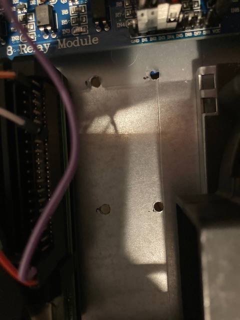
Drill holes in the chassis, install nylon standoffs, and add the section of plastic sheet.
-
Wire 4 of the 5 5V USB terminal "+" wires from the ATX breakout board to NC terminals on the 8 channel relay, and wire the other side of the relay to the "+" on the USB terminal block for 4 of the 5 Pi's. More relay setup instructions
-
Mount the 8 channel relay to the chassis with the nylon standoffs and secure with nylon nuts.
-
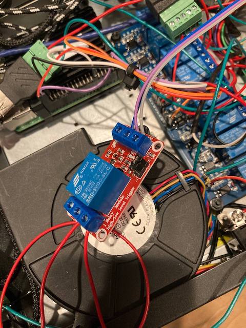
Cut a section of the plastic sheet that came with the chassis (for under the motherboard) to fit under the 1 channel relay board.
-
Drill holes in the chassis and install nylon standoffs for the 1 channel relay.
-
Wire DC+ on the relay to a 3.3V GPIO pin from a Pi that is powered by the 8 channel relay. DC- will need to be wired to a ground GPIO pin and IN will need to be wired to GPIO pin 18. Finally, wire the 5V power from the ATX breakout board to NC, and wire COM to the "+" on the terminal block for the Pi isn't powered by the 8 channel relay.
-
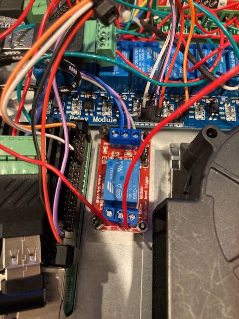
Mount the 1 channel relay to the chassis with the nylon standoffs and secure with nylon nuts.
-
Move the jumper on the 1 channel relay from H to L.
-
Plug one of ATX SATA power connectors into the fan controller and connect the blower fan from the chassis into the fan controller.
-
Drill a hole in the front of the case for the power switch and install the power switch.
-
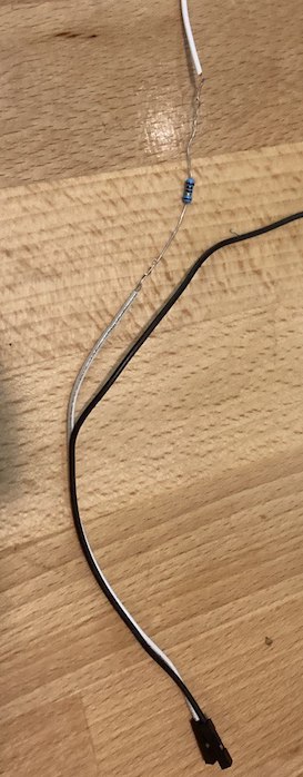
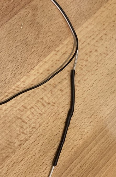
Add a 290 ohm resistor inline with a 6" length of wire with a female header on one side, add heatshrink, then strip the side opposite of the female header and install the wire into a 3.3V terminal on the ATX power supply breakout board.
-
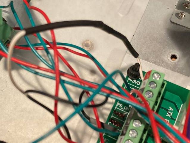
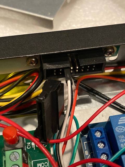
Add the stripped side of another wire of the same length with a female header on one side to a COM terminal on the power supply breakout board, then put the female headers onto the pins of one of the LEDs on the front panel.
-
Apply electrical tape over the unused header pins and terminal blocks to prevent accidental electrical shorts.
-
Connect the Pi's USB C ports to the USB terminal adapters.
-
Plug in the power and flip the power switch to "on".
Network Setup
- Get the static IPs, subnet, and gateway from the colocation provider.
- Edit
/etc/dhcpcd.confon each of the Pis and add the networking info from the colocation provider, for example:interface eth0 static ip_address=192.168.1.191/24 static routers=192.168.1.1 static domain_name_servers=8.8.8.8 8.8.4.4 -
sudo reboot
Remote Power Management Software
Only do this on the power management Paspberry Pi connected to the relay:
-
curl -o relay_control.py https://raw.githubusercontent.com/pawl/raspberry-pi-1u-server/main/relay_control.py - Test the script:
python relay_control.py
You should see the light on the SSD flash off and on for the Pi whose relay's GPIO pin you entered.
Measuring Amperage
- Plug the server into the Kill-A-Watt.
- Press the button on the Kill-A-Watt for "amps".
-
sudo apt-get install stress -
while true; do vcgencmd measure_clock arm; vcgencmd measure_temp; sleep 10; done& stress -c 4 -t 900s - Restart the server by unplugging and plugging back in. Watch the amperage on start-up.
Single Points Of Failure
- Switch
- Relay
- Power Supply
- Electrical Short (from loose terminal or pinched wire?)
- The Management Pi Dies (and can't powercycle most of the other Pi's)
How Many More Pi's Will Fit?
At least 7. (including 1 Pi Zero and a Pi 3b)
Cloud Comparisons
This is a tough comparison to make because the Pi CPU cores are only 1.5GHz per core.
AWS
- T2.micro - $9.50/month for 1GB Ram & 1 CPU @ 2.5 GHz * 20 = $190/month
- T2.medium - $38.00/month for 4GB Ram & 2 CPU @ 2.5 GHz * 10 = $380/month
The T2 instances have a limited number of CPU credits, which means they can't run at 100% all the time like the Pi can.
Digital Ocean
$20/month for 4GB Ram & 2 vCPUs @ 2.5 GHz * 10 = $200/month
Physical Server Comparisons
Dell R620
- Form Factor: 1U
- Power Consumption: 250W (not peak?) @ 120V = 2.08333A
- Cost: $585
- Specs:
- 2x E5-2630 V2 2.6Ghz = 12 cores
- 64GB RAM
- 4x 900GB SAS
Dell R710
- Form Factor: 2U
- Power Consumption: 160W (not at peak?) @ 120V = 1.33333A
- Cost: $688
- Specs:
- 2x E5649 2.53GHz = 12 cores
- 64GB RAM
- 16TB 4x 4TB
HoneyComb LX2
- Form Factor: 1U
- Power Consumption: 40W
- Cost: $750 + ($100 chassis, $250 RAM, $250 Hard Drives) = $1350
- Specs:
- 16 2.2 GHz cores
- 64GB RAM
- 16TB 4x 4TB
2x M1 Mac Minis
- Note: This will require running MacOS until full linux support.
- Form Factor: 1U
- Power Consumption: 80W (peak)
- Cost: ($700 * 2) + $100 chassis = $1500
- Specs:
- 16 3.2 GHz cores (insanely fast compared to Pis)
- 16GB RAM
- 512GB SSD Storage
Ideas For V2
- Add fuses and spade connectors inline with the devices to reduce the severity of an electical short.
Other Colocation Options
Other Chassis Options
-
BitScope Blade Rack
- Doesn't have as much room as the 1U chassis.
-
1U Raspberry Pi rack
- No room for storage, power supply, and a switch to allow for consolidating ethernet connections to the single cable required by the colocation provider.
- Doesn't match the usual server form factor, and some colocation providers might not like this?
- UCTRONICS Ultimate Rack with PoE Functionality for Raspberry Pi 4
- iStarUSA
- Dell R620
- Other options on Labgopher?
Other Single Board Computer Options
-
SOPINE Clusterboard
- Supports 7x compute modules, has a built-in switch, and can be powered by an ATX power supply.
- Out of stock at the time of writing (June 2021).
- Raspberry Pi CM4
- Back-ordered for months at the time of writing (June 2021).
- TuringPi 2 has not been launched yet as of June 2021.
-
RockPro64
- 6x CPU cores
-
Quartz64 Model B
- Has a built-in M.2 slot.
- ODROID-XU4
-
Banana Pi M4
- Built-in POE
- Mini-ITX motherboard with low-power processor
Other Case Options
- No case, drill holes for stand-offs, and mount to the chassis.
- More work, but would probably work fine and small heatsinks would be cheap.
-
Argon ONE M.2 Case for Raspberry Pi 4
- Includes an M.2 storage adapter.
Other Storage Options
- $44.99 - Samsung 860 EVO SSD 250GB M.2 SATA
- $60 - ORICO 128GB Mini M.2 NVME
- Fast NVMe drives might be bottlenecked by usb?
- http://pibenchmarks.com/popular/
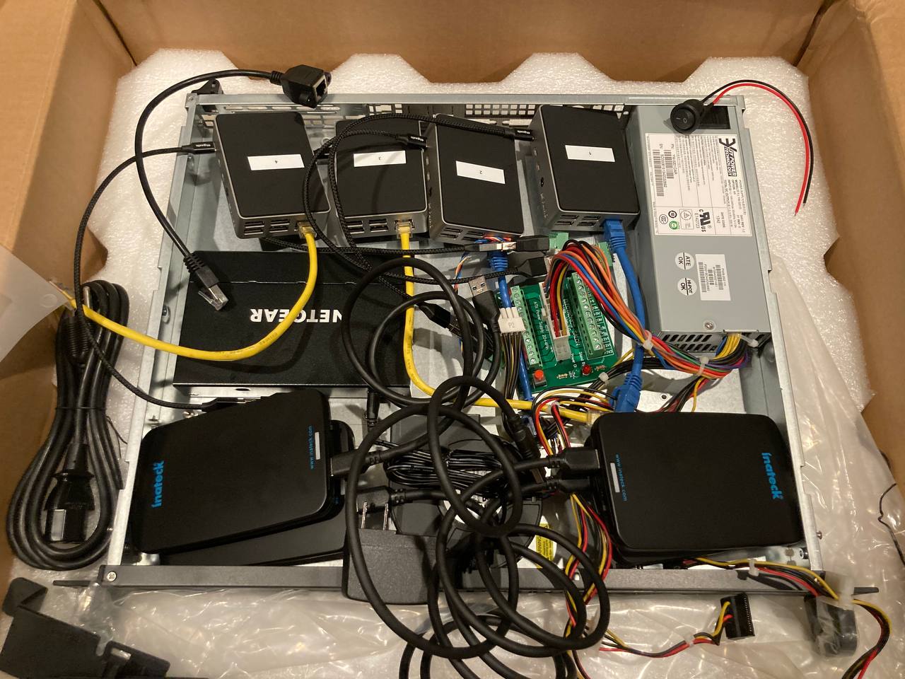
Note: I tried using 2.5" SSDs with inateck enclosures and there wasn't enough room.
Other Power Options
- USB Hub
-
Rosonway 16 Ports 100W USB 3.0 Data Hub
- Allows software control with uhubctl.
-
Rosonway 16 Ports 100W USB 3.0 Data Hub
- POE (maybe there are colocation providers that provide this for you?)
- $20 - (PoE+ HAT)[https://www.raspberrypi.org/products/poe-plus-hat/]
- At the time of writing (June 2021), the POE+ hat has some issues.
- POE switch
- $110 - Netgear GS108PP (supports POE+)
- $69.99 - NETGEAR 8-Port Gigabit Ethernet Unmanaged PoE Switch (GS308P) (no POE+, only 53W)
- $20 - (PoE+ HAT)[https://www.raspberrypi.org/products/poe-plus-hat/]
Other Power Switch Options
-
Toggle Switch With Safety Cover
- Less likely to poke an eye out or switch off accidentally.
